
Stator core and spindle motor including the same

Inactive Publication Date: 2013-04-25
SAMSUNG ELECTRO MECHANICS CO LTD
View PDF2 Cites 1 Cited by
  • Summary
  • Abstract
  • Description
  • Claims
  • Application Information

AI Technical Summary

Benefits of technology

The patent text describes a stator core that can reduce cogging torque and a spindle motor that includes this core. The technical effect of this innovation is to improve the performance of the motor by reducing the torque that causes uneven movement and improving the overall stability of the motor.

Problems solved by technology

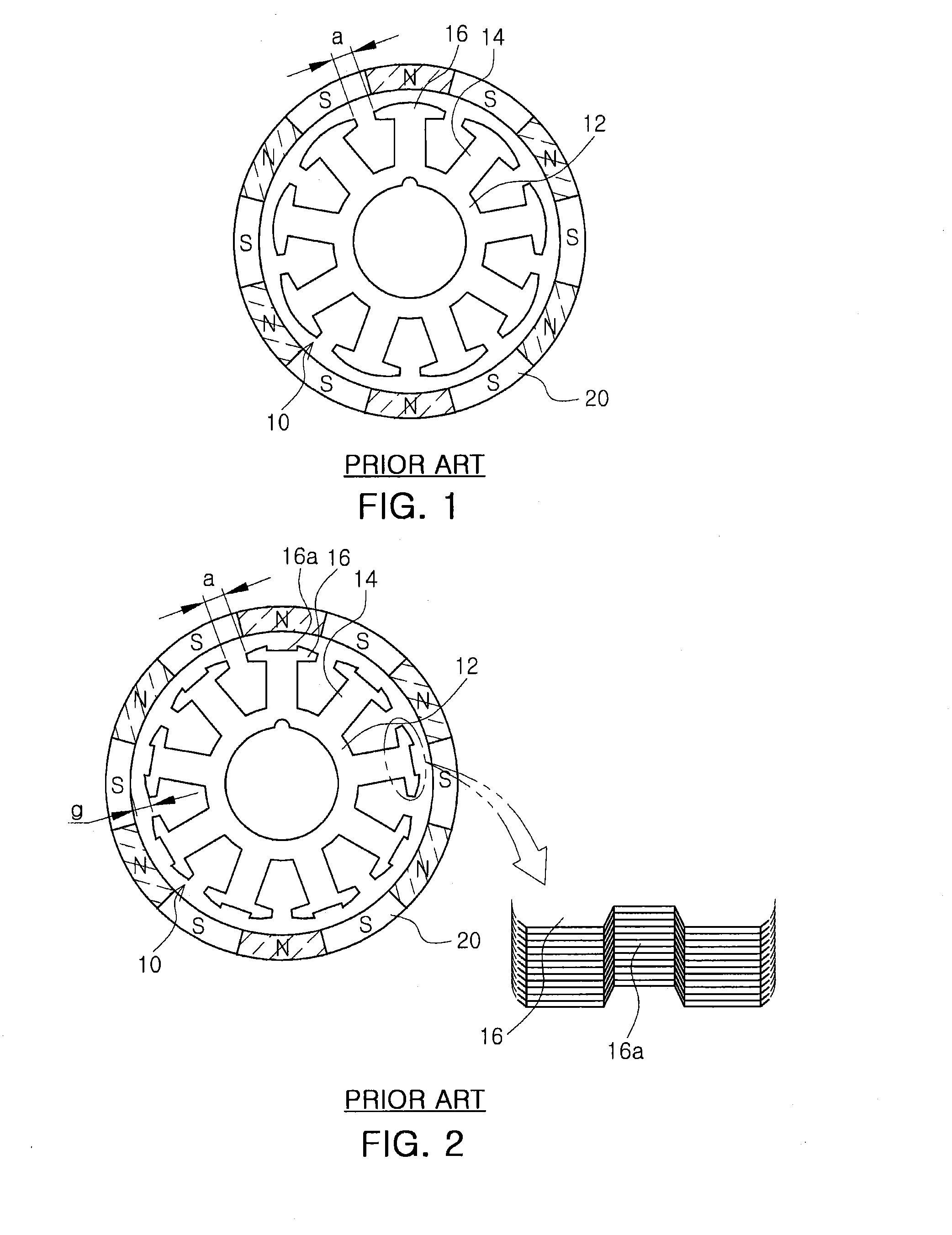
Therefore, vibrations and noise are generated at the time of the rotation of the rotor hub.
Therefore, noise such as a whistling sound, or the like, may additionally be generated.

Method used


Image

  • Stator core and spindle motor including the same
  • Stator core and spindle motor including the same
  • Stator core and spindle motor including the same

Examples


Embodiment Construction

[0033]Embodiments of the present invention will now be described in detail with reference to the accompanying drawings. However, it should be noted that the spirit of the present invention is not limited to the embodiments set forth herein and those skilled in the art and understanding the present invention can easily accomplish retrogressive inventions or other embodiments included in the spirit of the present invention by the addition, modification, and removal of components within the same spirit, but those are construed as being included in the spirit of the present invention.

[0034]Further, when it is determined that the detailed description of the known art related to the present invention may obscure the gist of the present invention, the detailed description thereof will be omitted.

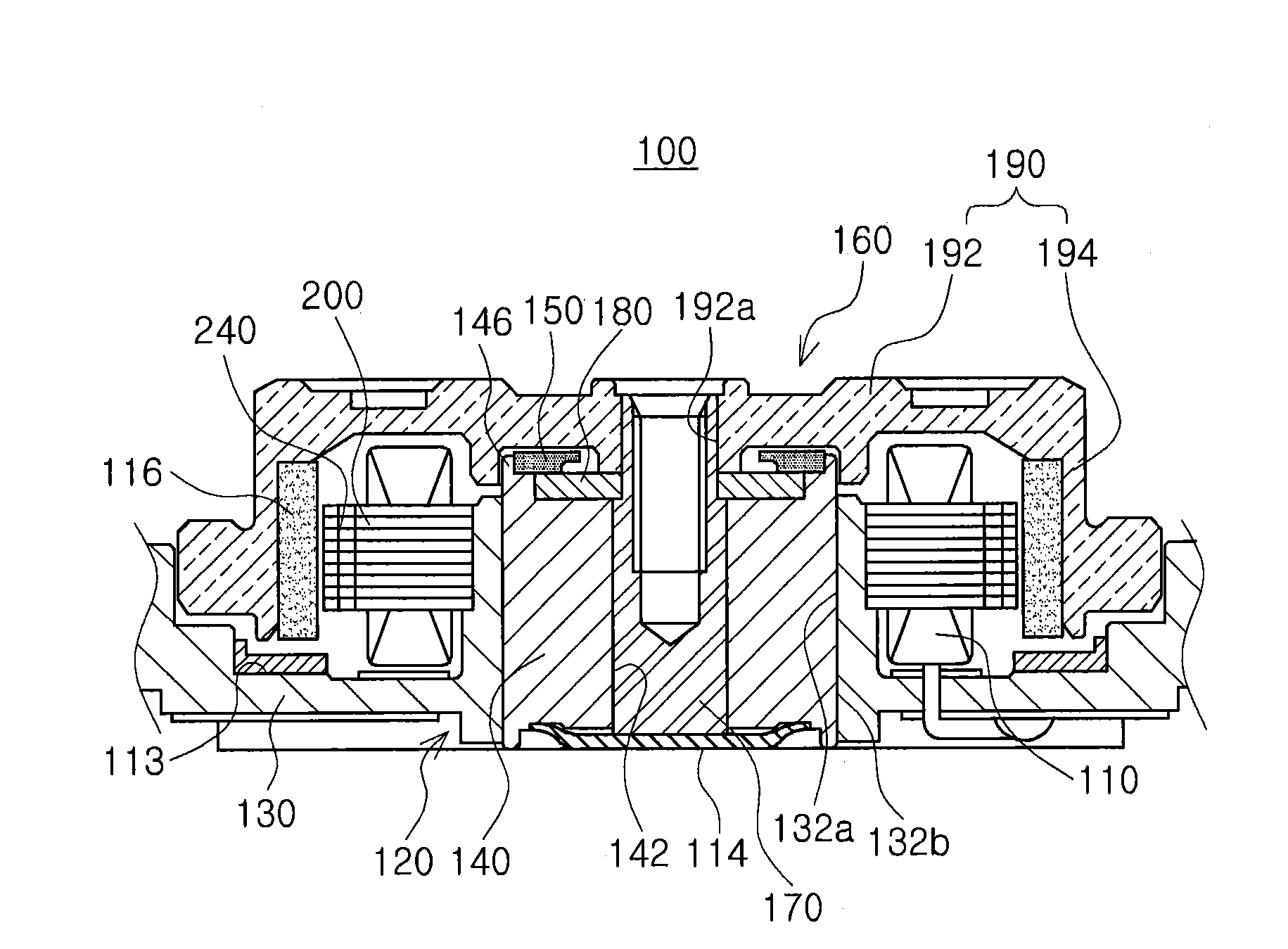
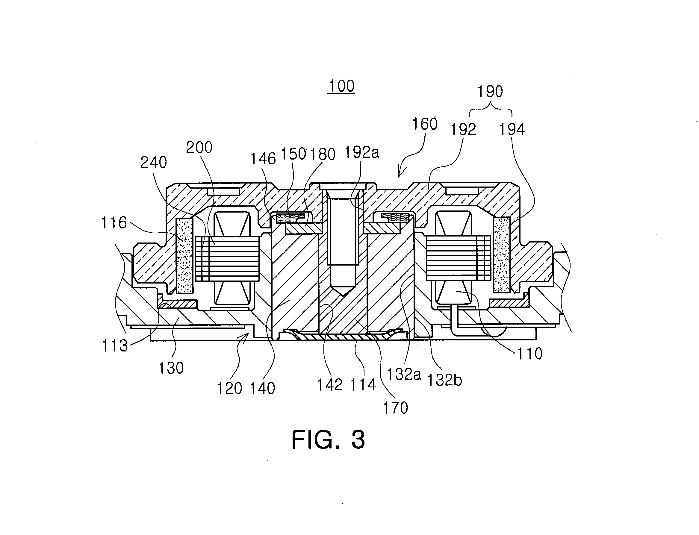
[0035]FIG. 3 is a schematic cross-sectional view showing a spindle motor according to an embodiment of the present invention.

[0036]Referring to FIG. 3, the spindle motor 100 according to the embodi...


PUM


Abstract

There is provided a stator core including: a coreback having an installation hole formed therein; a plurality of teeth extended from the coreback in a radial direction; and extension parts, each extended from each of the plurality of teeth in a circumferential direction and having a through-hole formed therein to reduce cogging torque.

Description

CROSS-REFERENCE TO RELATED APPLICATIONS[0001]This application claims the priority of Korean Patent Application No. 10-2011-0108441 filed on Oct. 24, 2011 in the Korean Intellectual Property Office, the disclosure of which is incorporated herein by reference.BACKGROUND OF THE INVENTION[0002]1. Field of the Invention[0003]The present invention relates to a stator core and a spindle motor including the same, and more particularly, to a stator core having a coil wound therearound and a spindle motor including the same.[0004]2. Description of the Related Art[0005]Generally, a small sized spindle motor used in a hard disk drive (HDD) may be configured of a rotor and a stator.[0006]Meanwhile, the rotor, a rotating member rotating while being supported by the stator, may include a rotor hub having a magnet installed thereon.[0007]In addition, the stator may include a stator core disposed to face the magnet, and is a fixed member for rotatably supporting the rotor.[0008]Further, the stator c...

Claims


Application Information

Patent Timeline
IPC IPC(8): H02K1/14
CPCG11B19/2009H02K1/146H02K29/03G11B19/20G11B33/08H02K1/18H02K15/02
Inventor OH, SONG BONOH, JONG RYEOL
Owner SAMSUNG ELECTRO MECHANICS CO LTD
Learn More