
Spindle motor, disk drive, and method of fabricating a stator core

A spindle motor and stator core technology, applied in electromechanical devices, manufacturing motor generators, electric components, etc., can solve problems such as large eddy current loss, low precision, and increased iron loss, and achieve reduced cogging torque and large capacity Recording and reducing the effect of iron loss

Inactive Publication Date: 2008-06-18
HITACHI LTD
View PDF2 Cites 9 Cited by
  • Summary
  • Abstract
  • Description
  • Claims
  • Application Information

AI Technical Summary

Problems solved by technology

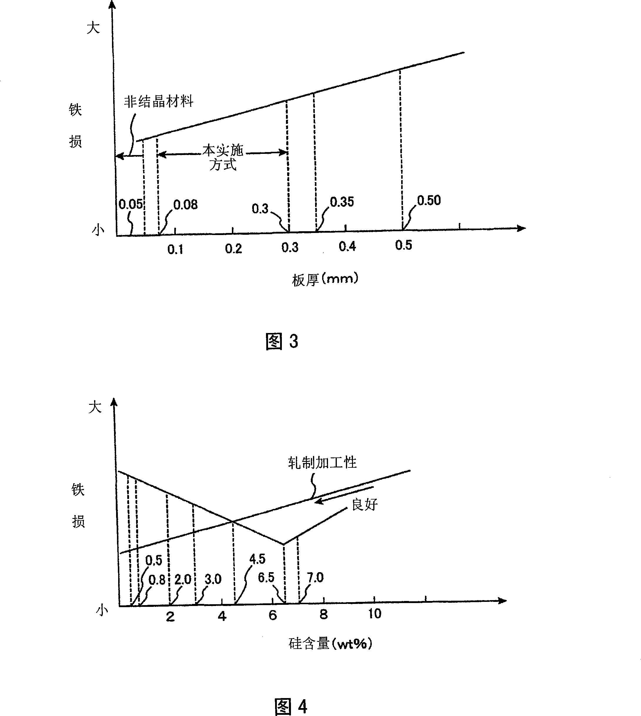
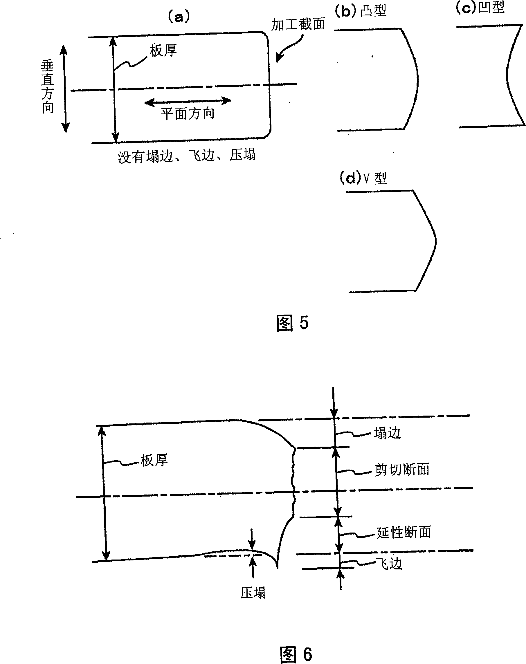
If the punching process is performed, the crystal structure of the cut part of the electrical steel sheet will be deformed, the magnetic properties will deteriorate, the inner area of ​​the hysteresis curve will increase, and the iron loss will increase.
In addition, the thick electrical steel sheet has a disadvantage of large eddy current loss, so there is a problem that the efficiency of the spindle motor cannot be improved.
[0013] In addition, in the punching process, the outer diameter of the motor is 10mm to 30mm even if it is large, and precision is required. On the contrary, because the precision of the punching process is not high, there is a disadvantage that the cogging torque cannot be improved.

Method used


Image

  • Spindle motor, disk drive, and method of fabricating a stator core
  • Spindle motor, disk drive, and method of fabricating a stator core
  • Spindle motor, disk drive, and method of fabricating a stator core

Examples


Embodiment Construction

[0032] Hereinafter, an embodiment of the present invention will be described with reference to the accompanying drawings.

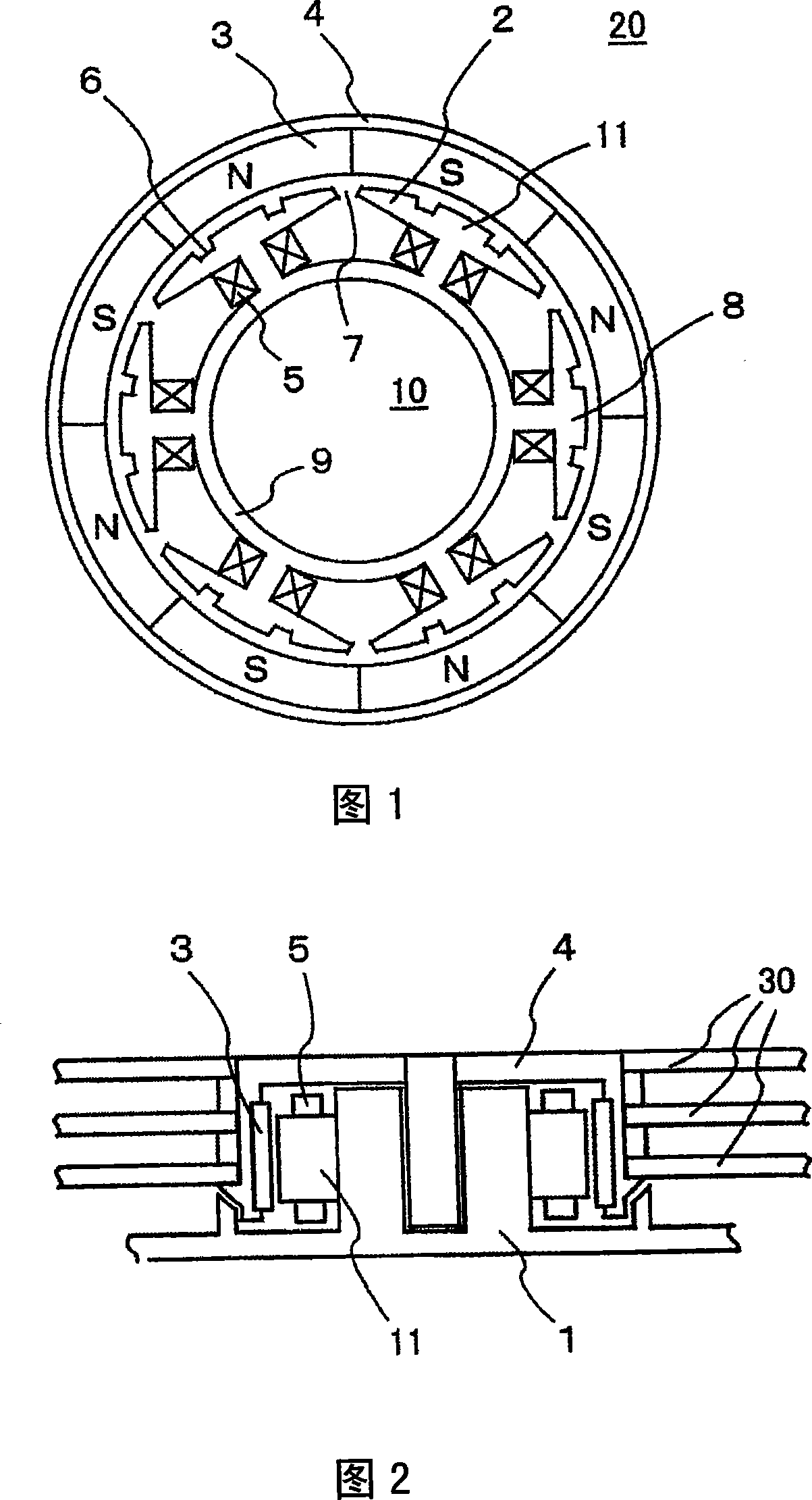
[0033] FIG. 1 shows a spindle motor according to a first embodiment of the present invention. The permanent magnet motor of this embodiment is an external type, and is a 4:3 structure spindle motor having an 8-pole rotor 20 and a 6-pole stator 10 . The rotor 20 has eight permanent magnets 3 and a hub 4 to which the permanent magnets 3 are fixed. The stator 10 has six salient poles 8 , and stator coils 5 are wound around the salient poles 8 . On the surface of the salient end 2 facing the permanent magnet 3 , correction grooves 6 are provided at two locations close to the center of the salient pole 8 . The detection method of the magnetic pole position of the permanent magnet 3 is omitted because it is not an essential problem, but there is also a brushless type in which a Hall element is provided on the housing 1 or an induced voltage generated in the s...


PUM

PropertyMeasurementUnit
thicknessaaaaaaaaaa
thicknessaaaaaaaaaa
thicknessaaaaaaaaaa

Abstract

The spindle motor has a stator and rotor. The stator has a stator core comprising a yoke and salient poles and also includes a stator coil. The stator core is formed by laminated steel sheets. The salient poles made of the steel sheets are formed by etching. The steel sheet is 0.05 to 0.30 mm thick. The steel sheet used in the present invention is preferably a silicon steel sheet having crystal particles. The iron loss and cogging torque of the inventive spindle motor are reduced.

Description

technical field [0001] The invention relates to a manufacturing method of a spindle motor, a disk drive device and a stator core. Background technique [0002] As the information recording capacity increases, it is necessary to reduce the size, increase the capacity, and increase the speed of HDDs and optical disc devices. And, for the convenience of portability, it is necessary to increase the use time of the storage battery once charged. One of the elements that determine the performance of this disk drive is the spindle motor. In order to achieve the above-mentioned improvement in performance, it is important to realize a spindle motor capable of high-efficiency, high-speed, and high-precision rotation. [0003] Here, firstly, it is important to reduce the cogging torque of the spindle motor in order to achieve a large capacity and high speed. Furthermore, in order to realize high efficiency and high speed, improving the efficiency of the spindle motor, especially redu...

Claims


Application Information

Patent Timeline
Patent Type & Authority Applications(China)
IPC IPC(8): H02K1/14H02K3/18H02K1/02H02K1/04G11B19/20H02K15/02H02K15/095
CPCY10T29/49009H02K15/022G11B19/2009G11B17/028G11B17/038H02K1/146
Inventor 田岛文男阿部辉宜伊藤元哉石川芳寿北村正司安岛俊幸
Owner HITACHI LTD
Learn More