Brushless motor

a brushless motor and high torque technology, applied in the direction of dynamo-electric machines, magnetic circuit rotating parts, magnetic circuit shapes/forms/construction, etc., can solve the problems of deteriorating steering feeling at non-energization, increase effective magnetic flux, reduce cogging torque, reduce air gap in the groove par

Inactive Publication Date: 2017-10-05
MITSUBA CORP
View PDF4 Cites 7 Cited by
  • Summary
  • Abstract
  • Description
  • Claims
  • Application Information

AI Technical Summary

Benefits of technology

[0014]According to the brushless motor of the present invention, the groove part is formed in the center of the tooth tip surface so as to be recessed, and the depth d and the width Wg of the groove part are set to satisfy 0<d≦(Lx−Rt) / 3 and Wt>Wg≧Wt / 2, respectively (Lx: distance between the center of the rotor and a tooth / slant intersection X which is the intersection between an extension line P of a circumferential side surface of the tooth main body and an extension line Q of a slope of the slant part, Rt: radius of the inner diameter of the tooth tip surface, Wt: width of the tooth main body). As a result, it is possible to magnetically saturate the slant part formed in a protruding manner at the tooth tip part, allowing the amount of magnetic flux flowing in the toothed part to be controlled. Further, the depth of the groove part is reduced, so that the air gap in the groove part can be reduced as compared with a conventional auxiliary groove having a large depth, which in turn can increase effective magnetic flux. As a result, there can be provided a high-torque and low-cogging torque brushless motor in which the amount of magnetic flux flowing in the toothed part can be controlled to reduce cogging torque, while ensuring torque.

Problems solved by technology

However, the EPS system has a problem that, when cogging torque of the motor is increased, steering feeling at non-energization is deteriorated.

Method used


Image

  • Brushless motor
  • Brushless motor
  • Brushless motor

Examples


Embodiment Construction

[0022]An embodiment of the present invention will be described below in detail with reference to the accompanying drawings. The object of the embodiment is to provide a high-torque and low-cogging torque brushless motor capable of reducing cogging torque while minimizing reduction in torque.

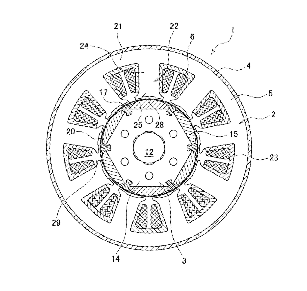
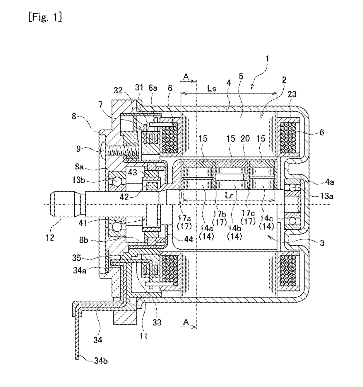
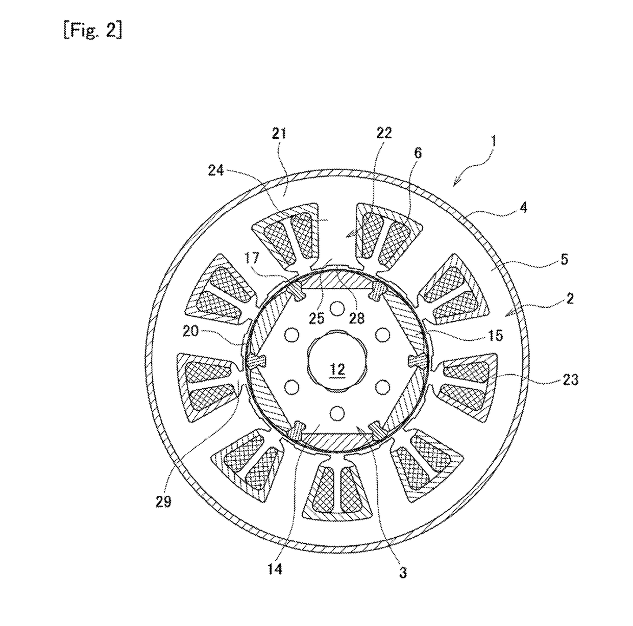
[0023]FIG. 1 is a cross-sectional view illustrating a configuration of a brushless motor 1 (hereinafter, abbreviated as “motor 1”) according to an embodiment of the present invention. FIG. 2 is a cross-sectional view taken along line A-A of FIG. 1. The motor 1 is used as, e.g., a power source for a column-assist type EPS. The motor 1 imparts an operation assist force to a steering shaft of an automobile while being normally and reversely rotated in accordance with the steering direction. As illustrated in FIG. 1, the motor 1 is an inner rotor type brushless motor in which a stator 2 is provide outside a rotor 3. The motor 1 is mounted to an unillustrated deceleration mechanism part provided in th...


PUM


Abstract

A brushless motor including a toothed part with a tooth main body and a tip part. Protruding slant parts are formed on both sides of the tooth tip part. A tip surface is formed on the inner diameter of the tip part to face a magnet. A groove part is recessed in the center of the tip surface and extends in the axial direction. A depth d of the groove part satisfies 0<d≦(Lx−Rt)/3. A width Wg of the groove part satisfies Wt>Wg≧Wt/2 (Lx: distance between rotor center and a tooth/slant intersection X; X: intersection between an extension line P of a circumferential side surface of the tooth main body and an extension line Q of a slope of the slant part; Rt: radius of the inner diameter of the tooth tip surface; Wt: width of the tooth main body).

Description

TECHNICAL FIELD[0001]The present invention relates to a high-torque and low-cogging torque brushless motor and, more particularly, to a brushless motor suitably applied to a drive source for an electric power steering device.BACKGROUND ART[0002]In recent years, many automobiles are equipped with a so-called power steering device for assisting a steering force. As the power steering device, an electric type power steering device (so-called electric power steering device: EPS) has prevailed recently under circumstances where engine load reduction, weight reduction, and the like are required. Although complicated control is required for a motor that serves as a power source for the electric power steering device, a brushless motor is preferably used from a viewpoint of easiness of maintenance. In recent years, with improvement of performance of a control element or controller, an EPS system using the brushless motor is becoming mainstream.[0003]However, the EPS system has a problem tha...

Claims


Application Information

Patent Timeline
Patent Type & Authority Applications(United States)
IPC IPC(8): H02K21/14H02K1/27H02K1/16
CPCH02K21/14H02K1/278H02K1/16H02K21/16H02K1/146H02K2201/03H02K2213/03
Inventor IKENO, HIROTATSUAOKI, TAKAMASAOGAWA, YUYA
Owner MITSUBA CORP
Why Eureka
Try Eureka