BLDC motor

a brushless dc motor and motor technology, applied in the direction of dynamo-electric machines, magnetic circuit rotating parts, magnetic circuit shape/form/construction, etc., can solve the problems of reduced reliability, reduced efficiency of motors, and reduced life, so as to improve the output density of motors and reduce the total harmonic distortion (thd). , the effect of improving the effective magnetic flux

Inactive Publication Date: 2019-09-03
SAMSUNG ELECTRONICS CO LTD
View PDF19 Cites 0 Cited by
  • Summary
  • Abstract
  • Description
  • Claims
  • Application Information

AI Technical Summary

Benefits of technology

[0011]The present disclosure provides a BLDC motor improving effective magnetic flux by forming a barrier capable of blocking leakage magnetic flux inside of a rotor in which permanent magnets which are radially disposed about a rotation shaft in the BLCD motor with the inside-disposed permanent magnet may cause the leakage magnetic flux about the one ends which are disposed to be adjacent to each other, and improving output density of the motor by reducing a total harmonic distortion (THD) of counter electromotive force and a torque ripple of the motor.
[0012]The present disclosure also provides a BLDC motor improving output density of the motor by reducing a total harmonic distortion (THD) of counter electromotive force and a torque ripple of the motor by allowing a shape of an end portion of a permanent magnet part to have an arc shape having the same center as an outer circumferential surface of a rotor and an inner circumferential surface of a stator to thereby increase effective magnetic flux and to prevent leakage magnetic flux.

Problems solved by technology

Since the DC motor includes a stator and a brush, it has a disadvantage that reliability is reduced and a lifespan is shortened due to a mechanical contact between the stator and the brush.
However, the BLDC motor with the inside-disposed permanent magnet having the V shape according to the related art as described above has a problem in that efficiency of the motor is decreased as leakage magnetic flux occurs through the inside of the rotor about portions at which the one ends of the permanent magnets disposed in the V shape are disposed to be too close to each other.
Also, the present disclosure is not required to overcome the disadvantages described above, and an exemplary embodiment of the present disclosure may not overcome any of the problems described above.

Method used


Image

  • BLDC motor
  • BLDC motor
  • BLDC motor

Examples


Embodiment Construction

[0036]The present disclosure will become apparent by describing exemplary embodiments of the present disclosure in detail with reference to the accompanying drawings. For reference, when it is determined that the detailed description of the known function or configuration related to the present disclosure may obscure the gist of the present disclosure in describing the present disclosure, the detailed description thereof will be omitted.

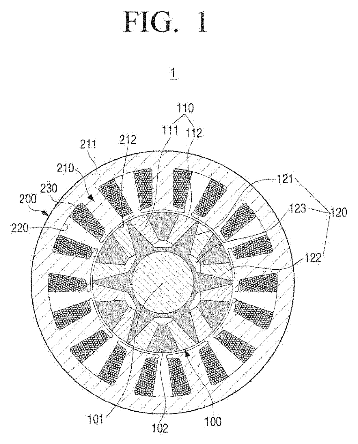
[0037]A rotor of a BLDC motor according to an exemplary embodiment of the present disclosure includes a plurality of permanent magnet parts. However, hereinafter, a case in which 6 permanent magnet parts are sequentially disposed along a cylindrical surface inside of the rotor while having polarity opposite to polarity of an adjacent permanent magnet part will be described by way of example.

[0038]FIG. 1 is a cross-sectional view of a BLDC motor 1 taken along a vertical direction of a rotation shaft, according to an exemplary embodiment of the present...


PUM


Abstract

The BLDC motor includes a stator, and a rotor disposed inside of the stator and including a plurality of permanent magnet parts, each of the permanent magnet parts including first and second permanent magnets which are disposed to have an interval therebetween. The rotor includes a slot part including a first portion into which the first permanent magnet is inserted, a second portion into which the second permanent magnet is inserted, and a third portion connecting the first and second portions to each other. The first and second portions have one end portions which are spaced apart from each other by a first distance and other end portions which are spaced apart from each other by a second distance which is shorter than the first distance, and the third portion connects the other end portions of the first and second portions to each other.

Description

CROSS-REFERENCE TO RELATED APPLICATIONS[0001]This application claims priority Korean Patent Application No. 10-2015-0141535, filed on Oct. 8, 2015, in the Korean Intellectual Property Office, the disclosure of which is incorporated herein by reference in its entirety.BACKGROUND[0002]1. Field[0003]Apparatuses and methods consistent with the present disclosure relate to a brushless DC (BLDC) motor, and more particularly, to a BLDC motor in which a rotor having a permanent magnet part is disposed inside of a stator.[0004]2. Description of the Related Art[0005]As is well known, a motor may be classified into a direct current (DC) motor and an alternating current (AC) motor depending on the power used. Since the DC motor includes a stator and a brush, it has a disadvantage that reliability is reduced and a lifespan is shortened due to a mechanical contact between the stator and the brush.[0006]Recently, a brushless DC (BLDC) motor with an inside-disposed permanent magnet in which the bru...

Claims


Application Information

Patent Timeline
Patent Type & Authority Patents(United States)
IPC IPC(8): H02K1/27
CPCH02K1/2766H02K1/2773
Inventor KIM, HONG-SEOKKO, BYOUNG-SOOKIM, YOUNG-KWANYOON, TAE-HOLEE, HYUNG-CHUL
Owner SAMSUNG ELECTRONICS CO LTD
Why Eureka
Try Eureka