

Motor
A technology of permanent magnets and components, applied in the direction of electric components, electrical components, electromechanical devices, etc., can solve the problems of reducing the working efficiency of the motor, reducing the stability of the rotor component of the motor, increasing the rotational load of the motor, etc., achieving high working efficiency, The effect of reducing radial wear and reducing radial force
- Summary
- Abstract
- Description
- Claims
- Application Information
AI Technical Summary
Problems solved by technology
Method used
Image

Examples
no. 1 example
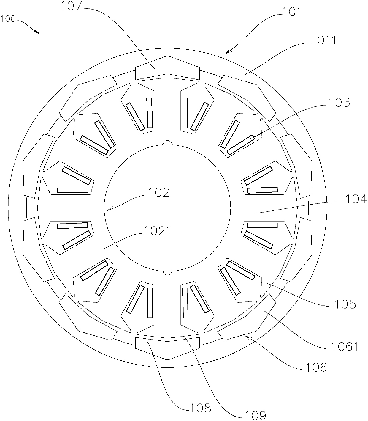
[0028] Such as figure 1 As shown, the motor 100 includes a rotor assembly 101 and a stator assembly 102 . The stator assembly 102 has a winding 103 and a magnetically permeable element 1021 , the magnetically permeable element 1021 is provided with a tooth 104 , and a crown 105 is formed on one end of the tooth 104 close to the permanent magnet. Along the radial direction of the motor 100 , the magnetic pole array 106 is equipped with a predetermined number of permanent magnets 1061 , and the permanent magnets 1061 of the magnetic pole array 106 are surface-attached on the inner surface of the rotor bracket 1011 of the rotor assembly 101 . Along the width direction of the permanent magnet 1061 , the thickness of the middle part of the permanent magnet 1061 is greater than the thickness of the two ends of the permanent magnet. The magnetic pole array 106 is located outside the tooth crown 105 , the working surface 107 of the permanent magnet 1061 close to the tooth crown 105 i...
no. 2 example
[0038] This embodiment is basically the same as the first embodiment, the difference lies in the number of winding arrays of the stator assembly and the number of magnetic pole arrays of the rotor assembly.
[0039] Such as Figure 8 As shown, the motor 200 is a dual-rotor motor, including a first magnetic pole array 201 , a second magnetic pole array 202 and a magnetically permeable element 203 of the stator assembly. The air gap between the permanent magnets of the first magnetic pole array 201 and the outer tooth crown 2031 of the magnetic permeable element 203, and the air gap between the permanent magnets of the second magnetic pole array 202 and the inner tooth crown 2032 of the magnetic permeable element 203 are all in waves The shape is evenly distributed along the circumference of the motor.
[0040] The motor can also be a double stator motor. Such as Figure 9 As shown, it includes a first magnetically permeable element 301 , a second magnetically permeable eleme...
no. 3 example
[0043] This embodiment is basically the same as the first embodiment, the difference is that teeth of different shapes are formed on the magnetic permeable element.
[0044] Such as Figure 11 , Figure 12 As shown, the magnetic permeable element 500 includes a tooth 501 , a crown 502 and a yoke 503 . The tooth width of the tooth 501 near the tooth crown 502 is greater than the tooth width of the tooth 501 near the yoke 503 . The tooth height of the tooth 501 close to the permanent magnet 504 is smaller than the tooth height of the tooth 501 close to the yoke 503 . At the same time, ensure that the cross-sectional area of the part of the tooth 501 between the tooth crown 502 and the yoke 503 is equivalent. It is beneficial to expand the slot width of the magnetic permeable element 500, to increase the conductive cross-sectional area of the winding, to increase the slot fullness rate, to increase the effective side length, to reduce resistance, to reduce copper consumpti...
PUM
 Abstract
Description
Claims
Application Information