motor

A technology of components and permanent magnets, which is applied in the direction of electromechanical devices, electrical components, electric components, etc., can solve the problems of increasing motor rotation load loss, reducing motor stability, and reducing motor working efficiency, so as to improve stability and weaken harmonics. wave, high efficiency effect

Active Publication Date: 2020-07-28
ZHUHAI PANLEI INTELLIGENT TECH CO LTD
View PDF9 Cites 0 Cited by
  • Summary
  • Abstract
  • Description
  • Claims
  • Application Information

AI Technical Summary

Problems solved by technology

However, the magnetic field strength between the permanent magnet and the teeth of the motor is relatively concentrated today, which reduces the stability of the rotor assembly of the motor, increases the rotational load loss of the motor, and reduces the working efficiency of the motor.

Method used


Image

  • motor
  • motor
  • motor

Examples


no. 1 example

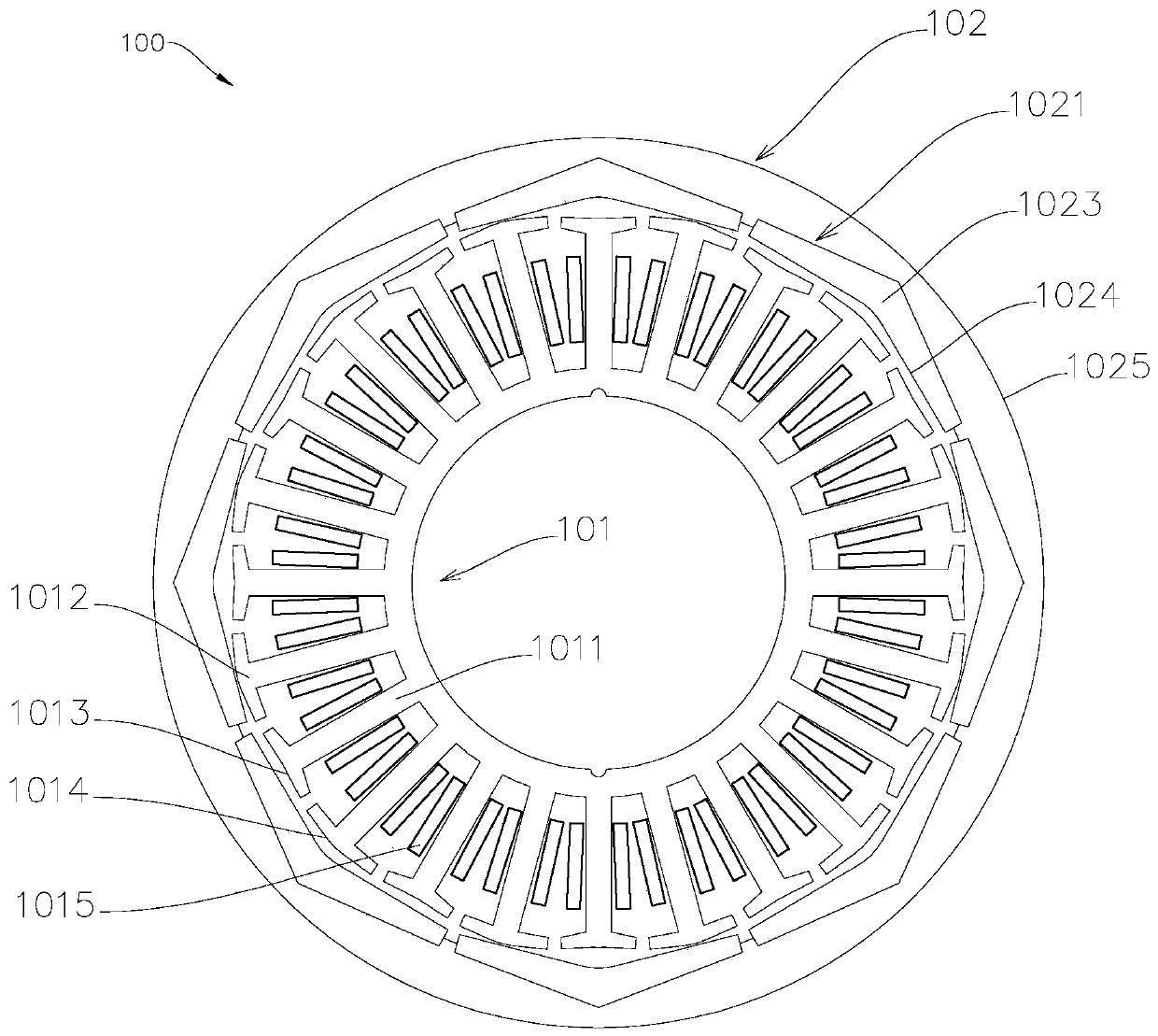
[0026] Such as figure 1 As shown, the motor 100 includes a stator assembly 101 and a rotor assembly 102 . The stator assembly 101 is provided with a magnetic conduction element 1011 , the magnetic conduction element 1011 is provided with teeth, and one end of the teeth facing the rotor assembly 102 is provided with a crown 1012 . The crown 1012 includes a concave crown 1013 and a convex crown 1014 . The concave tooth crown 1013 and the convex tooth crown 1014 are set at intervals, and the working surfaces of each three tooth crowns constitute the unit fluctuation variable in the fluctuation cycle of the convex surface, concave surface and convex surface in turn, so that the radial distance of the working surface of the stator assembly is along the circumferential direction. Has a fluctuating cycle. The rotor assembly 102 includes a permanent magnet array 1021 and a rotor bracket 1025 . Along the radial direction of the motor 100 , the permanent magnets 1023 of the permanent...

no. 2 example

[0032] This embodiment is basically the same as the first embodiment, the difference lies in the number of stator assemblies and rotor assemblies.

[0033] Such as Figure 5 As shown, the motor 500 is a dual-rotor motor, including a first permanent magnet array 501 , a second permanent magnet array 502 and a magnetic permeable element 503 of the stator assembly. Both the working surfaces of the first permanent magnet array 501 and the second permanent magnet array 502 have fluctuation periods. The number of teeth of the outer tooth crown 5031 and the inner tooth crown 5032 of the magnetic permeable element 503 of the stator assembly are equivalent, and both constitute a working surface with a fluctuation period. The working surface of the stator assembly and the working surface of the permanent magnet array work together to produce a thinner air gap with a fluctuating period, which is conducive to the construction of a large and uniform transition force, improves the stabilit...

no. 3 example

[0037] This embodiment is basically the same as the first embodiment, the difference is that teeth of different shapes are formed on the magnetic permeable element.

[0038] Such as Figure 7 , Figure 8As shown, the magnetic permeable element 700 includes a tooth 701 , a crown 702 and a yoke 703 . The tooth width of the tooth 701 near the crown 702 is greater than the tooth width of the tooth 701 near the yoke 703 . The tooth height of the tooth 701 close to the permanent magnet 704 is smaller than the tooth height of the tooth 701 close to the yoke 703 . At the same time, ensure that the cross-sectional area of ​​the part of the tooth 701 between the tooth crown 702 and the yoke 703 is equivalent. It is beneficial to expand the slot width of the magnetic permeable element 700, to increase the conductive cross-sectional area of ​​the winding, to increase the slot fullness rate, to increase the effective side length, to reduce resistance, to reduce copper consumption, and t...


PUM


Abstract

The invention provides a novel magnetic circuit structure motor. The motor comprises a stator assembly and a rotor assembly, wherein the stator assembly is provided with a winding and a magnetic conduction element, and the rotor assembly is fixed with an array of permanent magnets. The radial distance of the working surface of the stator assembly has a fluctuation variation period along the circumferential direction, and the radial distance of the working surface of the permanent magnet array has a fluctuation variation period along the circumferential direction. The width of the working surface of the permanent magnet of the permanent magnet array is at least 1.5 times the circumferential width of the working face of the crown of the stator assembly along the circumferential direction. When the permanent magnet and the teeth of the stator assembly move relative to each other, a finer air gap with a fluctuation period is generated between the working surface of the crown and the working surface of the permanent magnet, and the working efficiency of the motor is improved.

Description

technical field [0001] The invention relates to the field of motors, in particular to a motor with a novel magnetic circuit structure. Background technique [0002] A motor is a common driving device in daily life, which can convert electrical energy into mechanical energy. The motor includes a stator assembly and a rotor assembly, and the rotation of the rotor assembly relative to the stator assembly is realized by means of electromagnetic transformation, and the rotor assembly outputs power through a rotating shaft. However, the magnetic field strength between the permanent magnet and the teeth of the motor is relatively concentrated, which reduces the stability of the rotor assembly of the motor, increases the rotational load loss of the motor, and reduces the working efficiency of the motor. Contents of the invention [0003] The invention provides a motor with high working efficiency. [0004] To achieve the above object, the present invention provides a motor with ...

Claims


Application Information

Patent Timeline
Patent Type & Authority Patents(China)
IPC IPC(8): H02K1/16H02K1/27
CPCH02K1/165H02K1/2786H02K2213/03
Inventor 何春旺
Owner ZHUHAI PANLEI INTELLIGENT TECH CO LTD
Why Eureka
Try Eureka