Permanent magnet type synchronous motor

A technology of synchronous motors and permanent magnets, which is applied in the direction of synchronous motors with stationary armatures and rotating magnets, magnetic circuit rotating parts, magnetic circuit stationary parts, etc., and can solve problems such as the decrease of stator core magnetic force

Active Publication Date: 2007-07-18
SANKYO SEIKI MFG CO LTD
View PDF1 Cites 8 Cited by
  • Summary
  • Abstract
  • Description
  • Claims
  • Application Information

AI Technical Summary

Problems solved by technology

As a result, there is a problem that the mag...

Method used


Image

  • Permanent magnet type synchronous motor
  • Permanent magnet type synchronous motor
  • Permanent magnet type synchronous motor

Examples


Embodiment 1

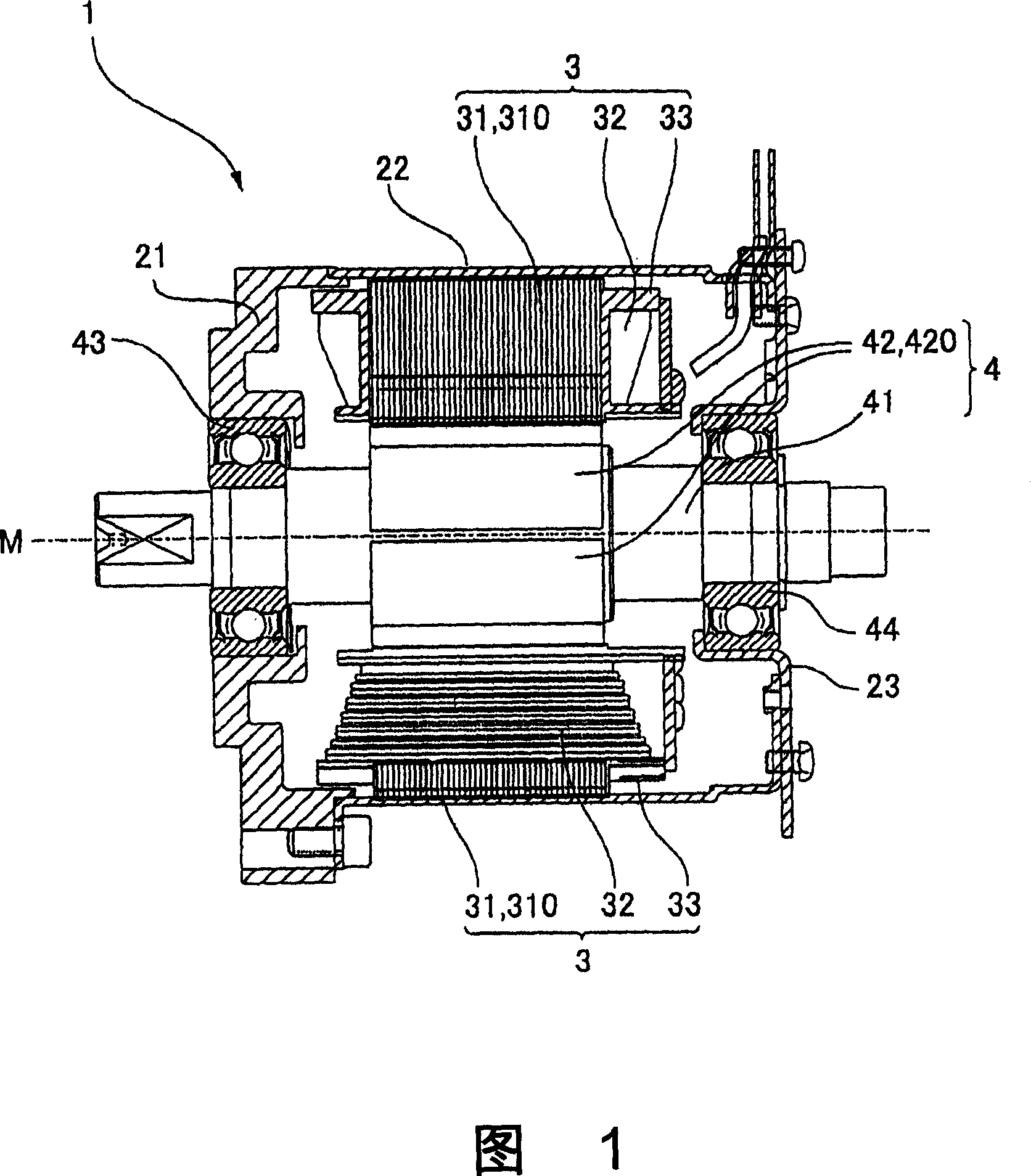
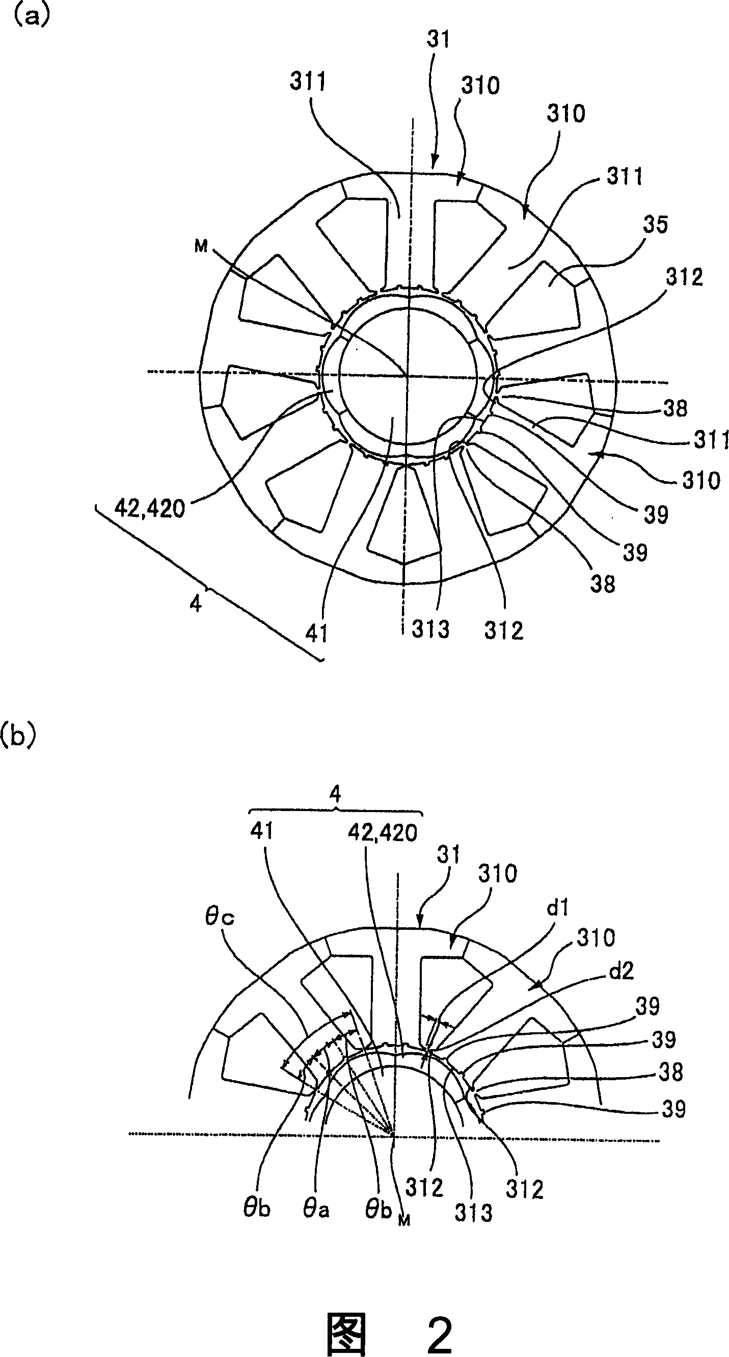
[0033] FIG. 1 is a cross-sectional view showing the configuration of a motor to which the present invention is applied. 2(a) and (b) are a cross-sectional view showing the configuration of a stator core to which the present invention is applied, and an explanatory diagram showing the configuration of an auxiliary slot, respectively.

[0034] (overall composition)

[0035] As shown in FIG. 1 , the motor 1 of this embodiment includes a cylindrical motor case 22 , a stator 3 arranged inside the motor case 22 , and a rotor 4 arranged inside the stator 3 . Both ends of the motor case 22 in the direction of the motor center axis M are open, and the bearing holding member 21 is attached to the motor case 22 so as to cover one of the openings, and the bearing holding member 23 is attached to cover the other opening. on the motor housing 22 . Therefore, the bearing holding member 21 and the bearing holding member 23 are used as housing members. The rotor 4 has a permanent magnet 42 ...


PUM


Abstract

The invnetion provides a permanent magnet synchronous motor, capable of preventing the magnetic force of a stator core from being reduced, and reducing the torque of a tooth space. In a motor (1), a stator core (31) comprises of a plurality of divided iron cores (310), a stator (4) has a divided permanent-magnet (420) mounted in the circumferential direction of a revolving shaft (41). In the divided iron cores (310), a gap (38) is formed between the front ends of the adjacent teeth (311), an auxiliary slot (39) is formed on the front end face (313), for dividing the the front end face (313) in the circumferential direction based on a equal angle.

Description

technical field [0001] The present invention relates to a permanent magnet synchronous motor (hereinafter referred to as a motor), and more particularly to a structure for reducing cogging torque (Japanese: kogingtoruk) in a permanent magnet synchronous motor. Background technique [0002] A permanent magnet type synchronous motor generally includes a stator and a rotor. The stator has a stator core in which a plurality of pole teeth protruding radially are arranged at equal angular intervals with slots interposed therebetween, and a stator core wound around the pole teeth. The rotor has permanent magnets, and the permanent magnets have S poles and N poles alternately arranged in the circumferential direction on the peripheral surface facing the front end surfaces of the pole teeth with a predetermined gap therebetween. [0003] In such a motor, cogging torque is generated by the magnetic attraction force acting between the stator core and the permanent magnets, and this cog...

Claims


Application Information

Patent Timeline
IPC IPC(8): H02K21/12H02K1/14H02K1/27
Inventor 高桥昌志泷本巌
Owner SANKYO SEIKI MFG CO LTD
Why Eureka
Try Eureka