Motor stator device

A motor stator and stator technology, applied in the manufacture of stator/rotor body, magnetic circuit shape/style/structure, magnetic circuit static parts, etc., can solve the problems of not conforming to the user, not easy to automate, and the coil is not so compact, etc.

Inactive Publication Date: 2007-08-01
JAGUAR PRECISION IND +1
View PDF0 Cites 8 Cited by
  • Summary
  • Abstract
  • Description
  • Claims
  • Application Information

AI Technical Summary

Problems solved by technology

The two types of motors mentioned above are not easy to be automated in production. Generally, the coils are wound outside the stator and then inserted into the slots. In this way, the coils will not be so compact, and have high terminal resistance like distributed windings. , In addition, if the thick wire is wound, there is still a large slot opening, so it still does not meet the needs of users in actual use.

Method used


Image

  • Motor stator device
  • Motor stator device
  • Motor stator device

Examples


Embodiment Construction

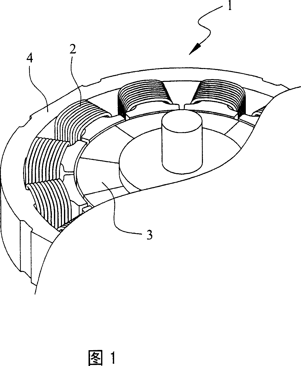
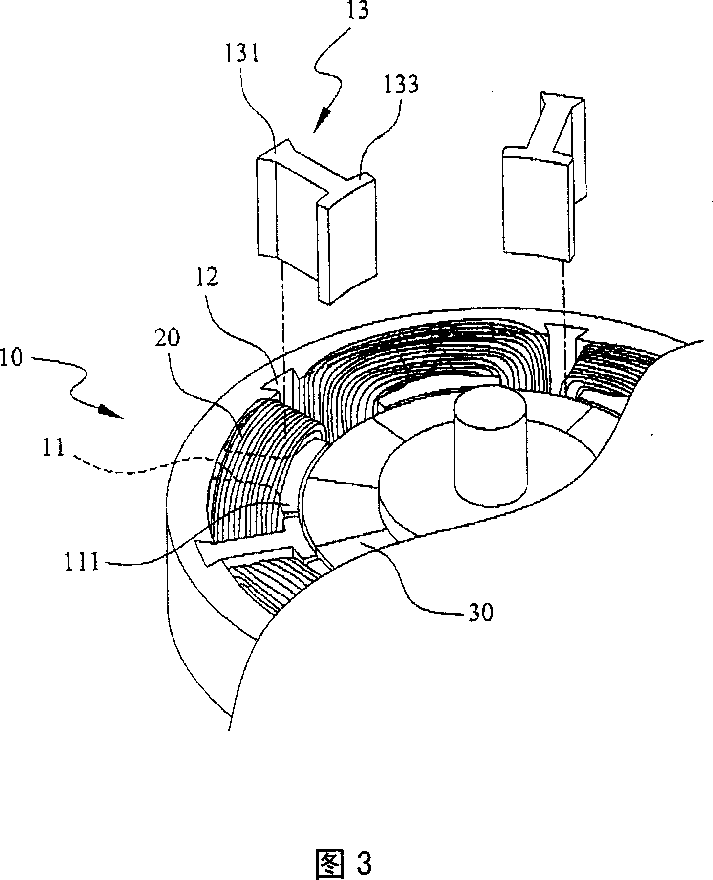
[0026] Please refer to Figures 2 to 4, the present invention is a motor stator device, the motor stator device includes:

[0027] A stator 10, the stator 10 is provided with a plurality of teeth 11, each tooth 11 is provided with an extension 111 at one end, and a positioning groove 12 is provided between two adjacent teeth 11 on the inner wall of the stator 10, each The positioning slot 12 is equipped with a tooth 13, and one end of the tooth 13 is provided with a coupling portion 131 for coupling to the positioning slot 12 on the inner wall of the stator 10, and the other end of the tooth 13 is provided with an extension portion 133, and The extension portion 133 of each tooth 13 is disposed corresponding to the extension portion 111 of each tooth portion 11 .

[0028] A plurality of coils 20 are provided, and each coil 20 is wound around each tooth portion 11 in the stator 10 .

[0029] A rotor 30 (the rotor is a magnet), and the rotor 30 is arranged inside the stator 10 f...


PUM


Abstract

The invention provides a motor stator device that comprises a stator, several loops and a rotor. Several tooth parts are set in the stator, and a locating slot is set between the adjacent two tooth parts of the stator wall, every locating slot is distributed with a tooth; every loop surrounds the tooth part of the stators; the rotor is set in inner of the stator for loop to generate electromagnetic attraction when electrified to make rotor rotating; it can increase the fill in ratio of wire, usage efficiency and decrease the rotating torque, but the rigidity will not be effected.

Description

technical field [0001] The present invention relates to a motor stator device, in particular to a design in which positioning grooves are provided between two adjacent teeth on the inner wall of the stator to separately arrange and combine each tooth, so as to improve the wire occupation rate, use efficiency and Reduce cogging torque and other effects, but do not reduce the overall rigidity, and are suitable for various motors or other similar devices. Background technique [0002] The existing motor device mainly includes a stator 1, a plurality of coils 2 and a rotor 3 (please refer to FIG. 1). The stator 1 is provided with a plurality of teeth 4, and each coil 2 is wound around each tooth 4 in the stator 1, and the rotor 3 is arranged inside the stator 1 to generate electromagnetic attraction when the coil 2 on the stator 1 is energized. force to drive the rotor 3 to rotate, but although it has the effect of rotation, the cogging gap between the teeth 4 provided in the s...

Claims


Application Information

Patent Timeline
Patent Type & Authority Applications(China)
IPC IPC(8): H02K1/16H02K15/02
Inventor 庄斐志
Owner JAGUAR PRECISION IND
Why Eureka
Try Eureka