Glue-injecting plunger structure for hydraulic motor
A hydraulic motor and glue injection technology, which is applied in the field of hydraulic motor plungers, can solve the problems of increasing time and reducing the rigidity of the hydraulic system, and achieve the effects of reducing inertial force, reducing moment of inertia, and reducing quality
- Summary
- Abstract
- Description
- Claims
- Application Information
AI Technical Summary
Problems solved by technology
Method used
Image
Examples
Embodiment
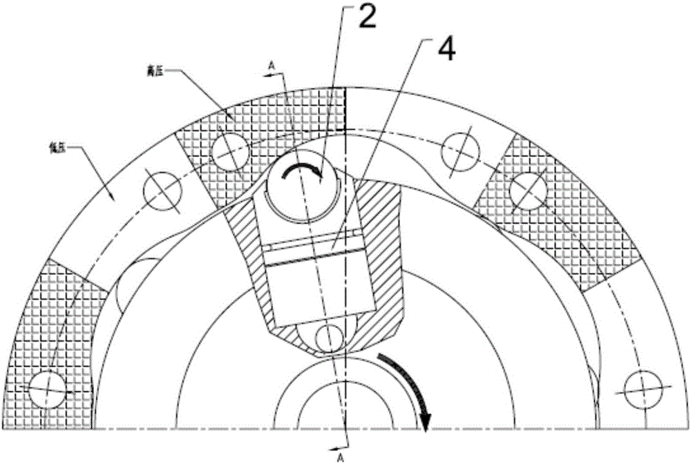
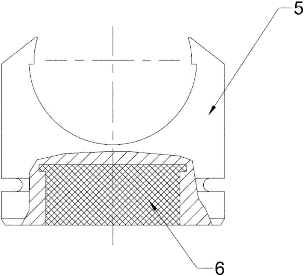
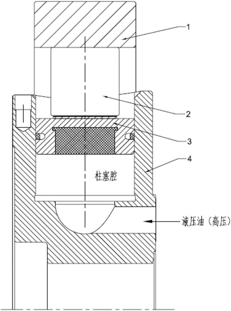
[0017] When the glue injection plunger 3 is in the high pressure area of the curved guide rail 1, the rotor body 4 is connected to the high pressure oil in the plunger cavity, and under the action of the high pressure oil, the glue injection plunger 3 is pushed out of the rotor plunger cavity, so that the roller 2 is in close contact with the rotor body. On the curved guide rail 1, and roll along the downward extension direction of the curved guide rail 1. When the injection plunger 3 is in the low-pressure area of the curved guide rail 1, it is connected to the low-pressure oil return in the plunger cavity of the rotor body 4. Since the pressure in the low-pressure area is lower than that in the high-pressure area, the rollers receive thrust when the curved guide rail 1 rises and the rollers 2 Push the injection plunger back into the rotor plunger chamber.
[0018] The original plunger is all made of metal parts, and the moment of inertia formed during the movement is rel...
PUM
 Abstract
Description
Claims
Application Information
 - R&D
- Intellectual Property
- Life Sciences
- Materials
- Tech Scout
- Unparalleled Data Quality
- Higher Quality Content
- 60% Fewer Hallucinations
Browse by: Latest US Patents, China's latest patents, Technical Efficacy Thesaurus, Application Domain, Technology Topic, Popular Technical Reports.
© 2025 PatSnap. All rights reserved.Legal|Privacy policy|Modern Slavery Act Transparency Statement|Sitemap|About US| Contact US: help@patsnap.com


