Motpor device capable of reducing cogging torque

a technology of motor devices and torque, applied in the direction of positive displacement liquid engines, piston pumps, magnetic circuit shapes/forms/construction, etc., can solve the problem of increasing the torque ripple, and achieve the effect of reducing the torque rippl

Inactive Publication Date: 2007-01-30
ASIA VITAL COMPONENTS SHENZHEN CO LTD
View PDF3 Cites 0 Cited by
  • Summary
  • Abstract
  • Description
  • Claims
  • Application Information

AI Technical Summary

Benefits of technology

[0007]A primary object of the present invention is to provide a motor capable of reducing cogging torque.

Problems solved by technology

However, the preceding stator device is easily to create cogging torque with the magnetic component and the greater the cogging torque is, the larger the torque ripple.

Method used


Image

  • Motpor device capable of reducing cogging torque
  • Motpor device capable of reducing cogging torque
  • Motpor device capable of reducing cogging torque

Examples


first embodiment

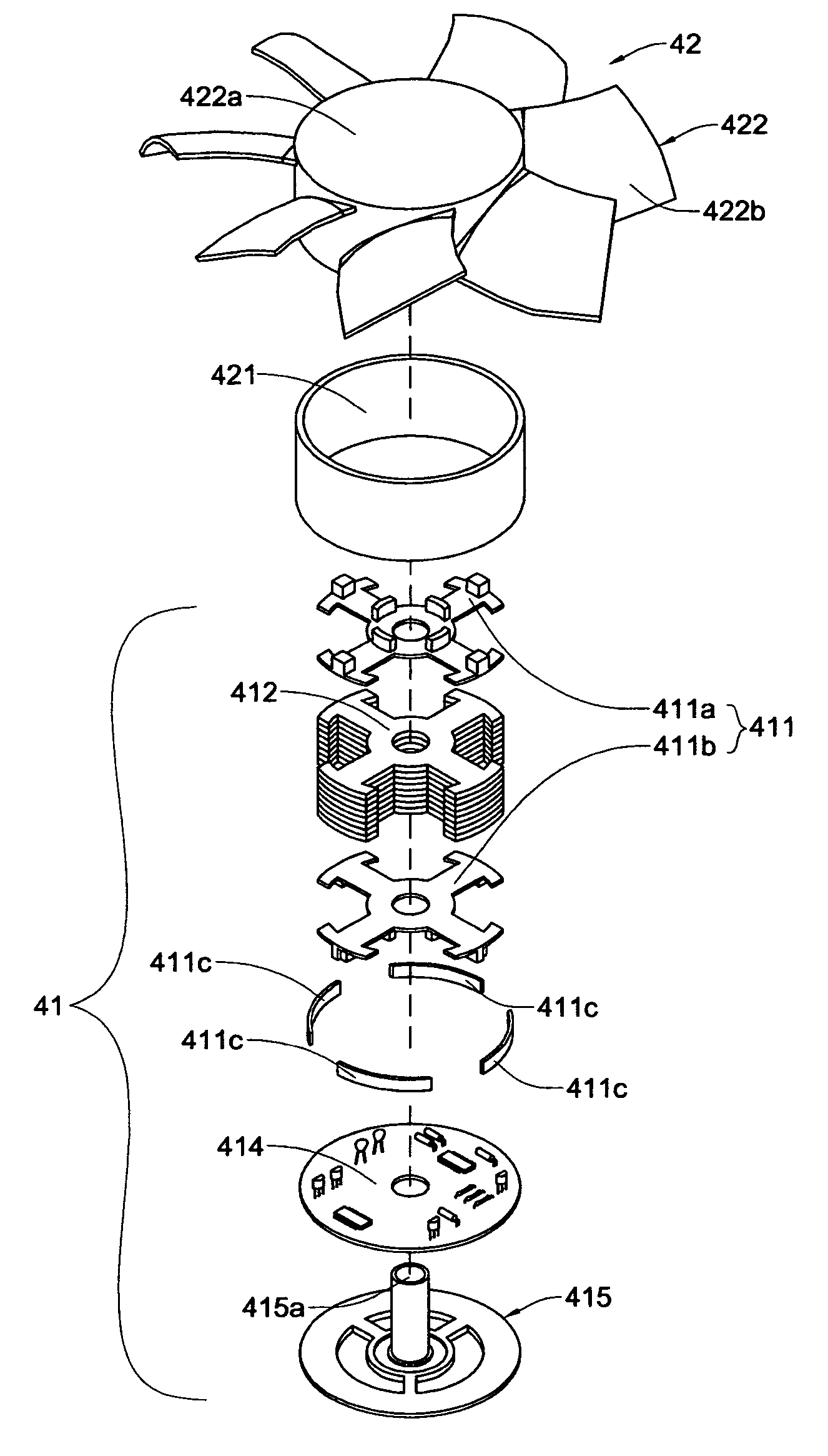
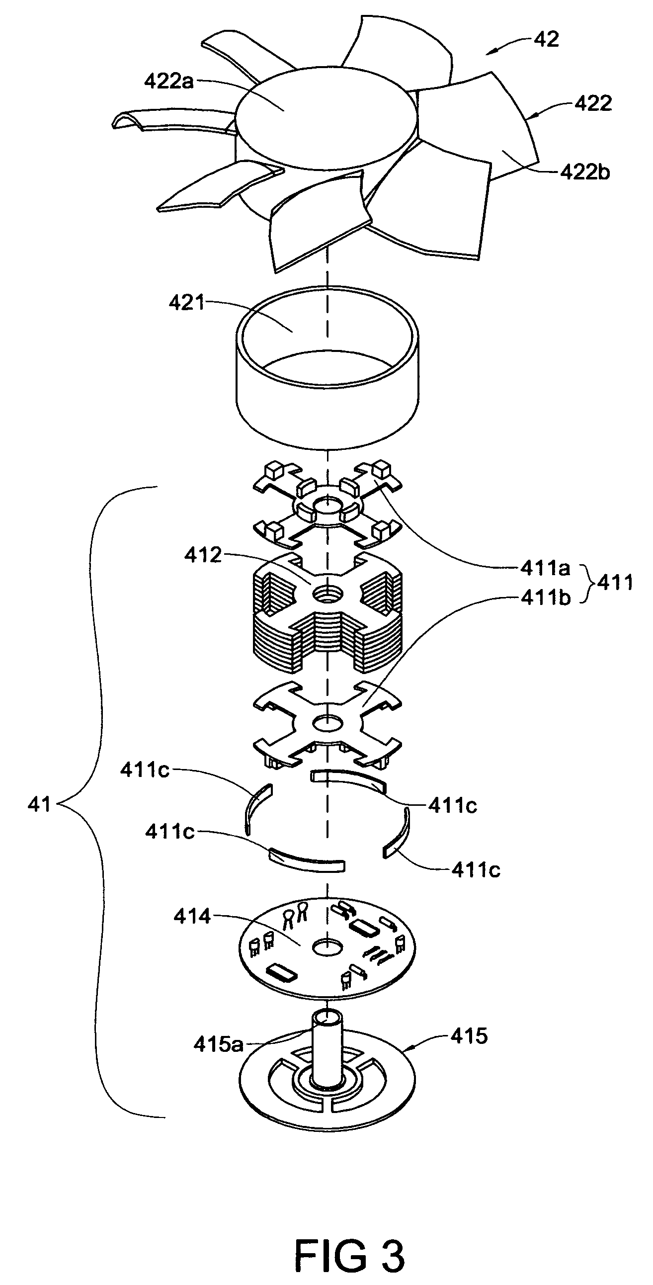
[0023]Referring to FIGS. 3, 4, 5 and 6, a motor device capable of reducing cogging torque according to the present invention includes a stator assembly 41 and a rotor assembly 42. The stator assembly 41 has a plurality of radial sections and further includes an insulation frame part 411, a plurality of silicone steel sheets 412, a coil 413, a circuit board 414 and a support part 415. The insulation frame part 411 is composed of art upper frame member 411a and a lower frame member 411b. The coil 413 is wound on the insulation frame part 411. a plurality of circular strip members 411c are provided at the bottom of the stator assembly 41 in a way of the respective circular strip member 411c having an end thereof being attached to the circumferential side of the lower frame member 411b and another end thereof extending to the sector shaped space, and the circular members 411c are disposed to space apart from each other in way of without contacting with the silicone steel sheets 412.

[002...

second embodiment

[0026]Referring to FIGS. 7, 8, 9 and 10, the motor device capable of reducing cogging torque according to the present invention includes a stator assembly 51 and a rotor assembly 52. The stator assembly 51 further includes an insulation frame part 511, a plurality of silicone steel sheets 512, a coil 513, a circuit board 514 and a support part 515. The insulation frame part 511 is composed of an upper frame member 511a and a lower frame member 511b. The coil 513 is wound to the insulation frame part 511 and a ring member 511c is attached to the lower frame member 511b. The circular member 511c has a plurality of projections 511d and the projections 511d are disposed to space apart the silicone steel sheets 512 in a way of not contacting with the silicone steel sheets 512 The rotor assembly 52 includes a magnetic component 521, a fan blade part 522 and a rotational shaft 522. The fan blade part 522 is composed of a hub member 522a and a plurality of fan blades 522b circumferentially ...

third embodiment

[0028]Referring to FIGS. 11, 12, 13 and 14, the motor device capable of reducing cogging torque according to the present invention includes a stator assembly 61 and a rotor assembly 62. The stator assembly 61 further includes an insulation frame part 611, a plurality of silicone steel sheets 612, a coil 613, a circuit board 614 and a support part 615. The insulation frame part 611 is composed of an upper frame member 611a and a lower frame member 611b. The coil 613 is wound to the insulation frame part 611 and the circuit board 614 is provided with a plurality of circular members 614c. The circular members 614c are disposed to space apart the silicone steel sheets 612 in way of not contacting with the silicone steel sheets 612. The rotor assembly 62 includes a magnetic component 621, a fan blade part 822 and a rotational shaft 622. The fan blade part 622 is composed of a hub member 622a and a plurality of fan blades 622b circumferentially attached to the hub member 622a. The magneti...


PUM


Abstract

A motor device capable of reducing cogging torque includes a stator assembly and a rotor assembly, which is movably disposed in the stator assembly. The rotor assembly provides a magnetic component. The stator assembly further includes an insulation frame part, a set of silicone steel sheets and a coil winding the insulation frame. A plurality of circular strip members are disposed at the circumferential side of the bottom of the stator assembly in a way of the respective circular strip member has an end thereof being attached to the bottom of the insulation frame part and another end thereof extending circumferentially to the sector shaped space. Further, the circular strip members space apart from each other without contacting the silicone steel sheets.

Description

BACKGROUND OF THE INVENTION[0001]1. Field of the Invention[0002]The present invention is related to a motor device capable of reducing cogging torque and particularly to a structure of the stator in a motor able to reduce cogging torque.[0003]2. Brief Description of the Related Art[0004]Referring to FIGS. 1 and 2, the conventional motor includes a stator device 11 and a otor device 12. The stator further includes an insulation frame 111, a set of silicone steel sheet 112, a coil 113, a circuit board 114 and a support part 115. The insulation frame 111 is composed of an upper frame member 111a and a lower frame member 111b. The coil 113 is wound to the insulation frame 111. The rotor device 12 further includes a magnetic component 121, a fan blade part 122 and a rotational shaft 123. The fan blade part 122 is composed of a hub section 122a and a plurality of fan blades 122b attached to the circumference of the hub section 122a. The magnetic component 121 and shaft 123 are disposed in...

Claims


Application Information

Patent Timeline
Patent Type & Authority Patents(United States)
IPC IPC(8): H02K5/24H02K11/00H02K7/00
CPCH02K29/03
Inventor HO, CHUN-LIANGYANG, CHING-MIN
Owner ASIA VITAL COMPONENTS SHENZHEN CO LTD
Why Eureka
Try Eureka