A ring magnet unit for an electric motor

a technology of electric motors and ring magnets, applied in the direction of magnetic bodies, dynamo-electric machines, magnetic circuit shapes/forms/construction, etc., can solve the problems of difficult to secure the fixing of a ring magnet into a housing, and achieve the effect of simple and high-efficiency magnetic circuits, increasing the power of electric motors without increasing their length

Inactive Publication Date: 2018-08-23
NIDEC MOTORS & ACTUATORS GERMANY
View PDF4 Cites 1 Cited by
  • Summary
  • Abstract
  • Description
  • Claims
  • Application Information

AI Technical Summary

Benefits of technology

[0003]An object of the invention is to achieve a highly efficient magnetic circuit in a simple and inexpensive manner. A further object of the invention is to increase the power of electric motors without increasing their length while reducing the cogging torque in a simple and inexpensive manner.

Problems solved by technology

Therefore, fixing a ring magnet into a housing securely is difficult.

Method used


Image

  • A ring magnet unit for an electric motor
  • A ring magnet unit for an electric motor
  • A ring magnet unit for an electric motor

Examples


Embodiment Construction

[0033]The object of the present invention is fully described below using examples for the purpose of disclosure, without limiting the disclosure to the examples. The examples present different aspects of the present invention. To implement the present technical teaching, it is not required to implement all of these aspects combined. Rather, a specialist will select and combine those aspects that appear sensible and required for the corresponding application and implementation.

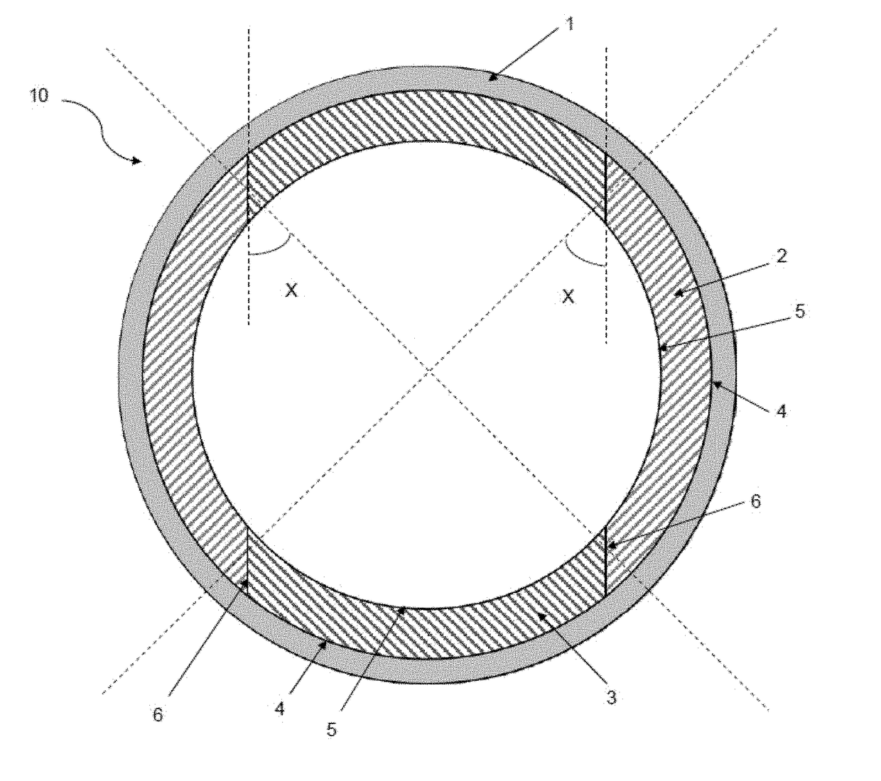
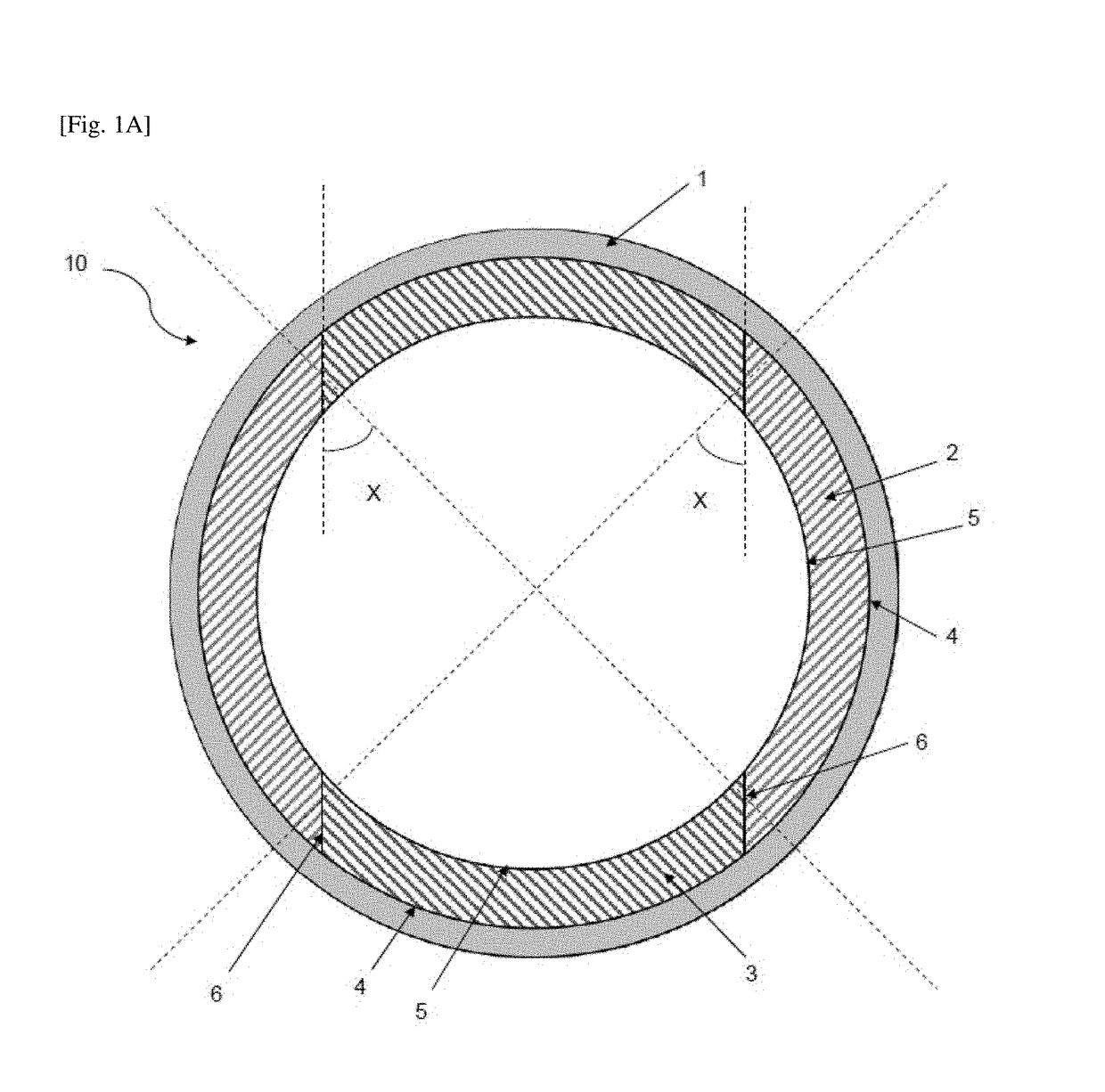
[0034]FIG. 1A shows a cross sectional view of a ring magnet unit 10 in accordance with a first embodiment. The ring magnet unit 10 comprises a circular magnet holder 1 and at least two magnet segments 2, 3. FIG. 1A shows a pair of a first magnet segment 2 and a pair of a second magnet segment 3, but the present invention is not limited to this configuration. FIG. 1A shows that the pair of the first magnet segment 2 is fixed to the magnet holder 1 and arranged in a circumferential direction of the magnet holder ...


PUM


Abstract

A ring magnet unit for an electric motor is provided, comprising a circular magnet holder and at least two magnet segments fixed to the magnet holder and arranged in a circumferential direction of the magnet holder, wherein respective one magnet segment has a first surface abutting to a surface of the magnet holder and a second surface which is the opposite surface of the first surface. Both side surfaces of the first surface and the second surface are chamfered in the directions that cross the radial direction of the magnet holder at the same angles. At least one pair of the adjacent two magnet segments comprises one magnet segment whose circumferential length of the first surface is equal to or longer than the circumferential length of the second surface and the other magnet segment whose circumferential length of the first surface is equal to or shorter than the circumferential length of the second surface.

Description

BACKGROUND OF THE INVENTION1. Field of the Invention[0001]The invention refers to a ring magnet unit and an electric motor therewith. Specifically, the invention refers to a ring magnet unit comprising plural magnet segments and plural magnetic fields.2. Description of the Related Art[0002]In brushed motors normally single ferrite magnets or low grade ring magnets, for example plastic bonded neodymium, ring magnets are used and in brushless motors usually a rotor built with low grade ring magnets is used. One example of a ring magnet having outer polygonal shape is disclosed in US 2010 / 102662 A1. Furthermore, attempts have been made to build up electrical motors by arranging magnet segments to build up a ring like shape, wherein gaps are at least partly arranged in the magnet segments in a circumferential direction. DE 3 521 005 A1 discloses a motor having four segments, arranged in mutually abutting pairs, gaps being arranged between said pairs.SUMMARY OF THE INVENTION[0003]An obje...

Claims


Application Information

Patent Timeline
Patent Type & Authority Applications(United States)
IPC IPC(8): H02K1/27
CPCH02K1/2733H02K2201/06H02K29/03H01F7/0221H02K1/278H02K1/2791
Inventor SCHMID, JUERGEN
Owner NIDEC MOTORS & ACTUATORS GERMANY
Why Eureka
Try Eureka