Slide wiring device

a wiring device and slide technology, applied in the direction of movable seats, cable arrangements between relatively moving parts, transportation and packaging, etc., can solve the problems of resin rails lacking strength, corrugated tubes may suffer wear, and particularly problematic wear of corrugated tubes, so as to suppress the damage of armoring members

Active Publication Date: 2019-02-26
AUTONETWORKS TECH LTD +2
View PDF16 Cites 7 Cited by
  • Summary
  • Abstract
  • Description
  • Claims
  • Application Information

AI Technical Summary

Benefits of technology

[0006]The present design was made in view of the above-described circumstances, and it is an object thereof to provide a slide wiring device in which the damage of an armoring member is suppressed.
[0008]According to the technique disclosed in the present description, the armoring member moves on the resin rail, and thus does not need to come into sliding contact with (be confined by) the metal rail. Accordingly, even if the metal rail is used, it is possible to confine the movement of the wire harness while suppressing the damage of the armoring member.
[0011]According to the above-described aspect, the engaging portion is configured to be reliably facilitated to enter the groove portion by the entry-facilitating portion. Accordingly, when the engaging portion is inserted into the groove portion, the collision of the armoring member with the resin rail is suppressed, thus making it possible to further suppress the damage of the armoring member.
[0013]According to the above-described aspect, even if a foreign object such as sand or gravel stone has entered the groove portion, the object is promptly discharged from the through hole to the outside of the groove portion. It is possible to suppress the armoring member from colliding with and being damaged by the foreign object that has entered the groove portion.
[0015]According to the above-described aspects, it is possible to keep the armoring member from interfering with the fixing member. Accordingly, it is possible to reliably suppress the damage of the armoring member.
[0016]The present design was made in view of the above-described circumstances, and it is an object thereof to provide a slide wiring device in which the damage of an armoring member is suppressed.

Problems solved by technology

In such a case, there is some concern that the corrugated tube may suffer wear due to its outer surface being in sliding contact with the rail.
Wear of the corrugated tube is particularly problematic if the rail is made of metal.
However, the sliding part such as a sliding seat is relatively heavy, and thus there is the risk that a resin rail lacks strength.

Method used


Image

  • Slide wiring device
  • Slide wiring device
  • Slide wiring device

Examples


embodiment 1

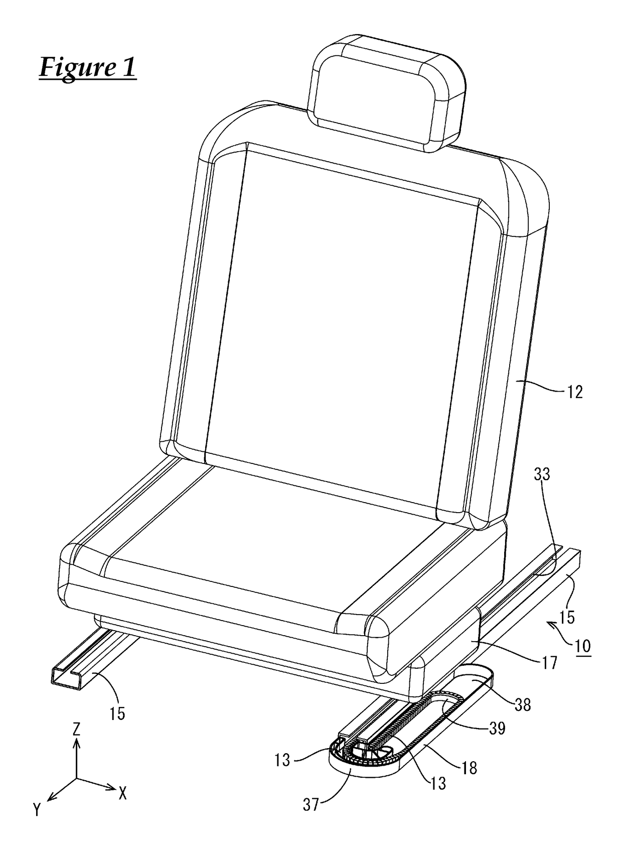
[0034]Embodiment 1 of the present design will be described with reference to FIGS. 1 to 17. A slide wiring device 10 according to the present embodiment is used for a wire harness 13 to be arranged between a vehicle body 11 and a seat 12 of a vehicle such as an automobile (not shown). In the following, a description will be given assuming that the X direction of FIG. 1 refers to a “right” direction, the Y direction refers to a “front” direction, and the Z direction refers to an “up” direction.

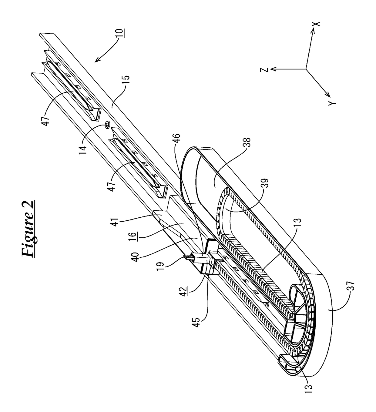
[0035]As shown in FIG. 2, the seat 12 is slidable in the front-rear direction with respect to a metal rail 15 that is made of metal and is fixed to the vehicle body 11 with bolts 14 (an example of a fixing member). The seat 12 is provided with various types of electric components such as, for example, an electrically-driven reclining device, a seat heater, a sensor for detecting whether or not a passenger is seated, and a sensor for detecting whether or not a seat belt is worn. As shown in FIG....


PUM


Abstract

A slide wiring device includes: a metal rail; a slider slidably arranged on the metal rail; a wire harness in which a plurality of electric wires are armored by an armoring member made of a resin, the wire harness being coupled to the slider and configured to move in the metal rail along with movement of the slider; and a resin rail that is arranged inside the metal rail, and is configured to confine movement of the armoring member. The armoring member is configured to move on the resin rail along with the movement of the slider.

Description

CROSS REFERENCE TO RELATED APPLICATIONS[0001]This application claims the priority of Japanese patent application JP2015-195704 filed on Oct. 1, 2015, the entire contents of which are incorporated herein.TECHNICAL FIELD[0002]The present description provides a technique relating to a slide wiring device.BACKGROUND ART[0003]Conventionally, a slide wiring device disclosed in Patent Document 1 (JP2013-42658A) is known as a slide wiring device that electrically connects a vehicle and a sliding part such as a sliding seat installed in the vehicle. This slide wiring device is provided with: a rail; a slider slidably attached to the rail; and a wire harness that is arranged in the rail and has one end portion coupled to the slider. The wire harness is obtained by accommodating a plurality of electric wires in a corrugated tube.SUMMARY[0004]According to the above-described configuration, when, for example, the slider moves back and forth, also the wire harness coupled to the slider moves alon...

Claims


Application Information

Patent Timeline
Patent Type & Authority Patents(United States)
IPC IPC(8): B60R22/34B60R16/02B60N2/90B60R16/027B60N2/06B60R22/26H02G11/00H02G3/04
CPCB60R16/027B60N2/06B60N2/90B60R22/26B60R22/34H02G11/006B60R16/0215H02G3/0468H02G3/0475B60N2/0715B60N2/0264
Inventor YAMAMOTO, SATOSHITOMOYUKI, SAKATAHIGASHIKOZONO, MAKOTO
Owner AUTONETWORKS TECH LTD
Why Eureka
Try Eureka