Mapping of fracture geometries in a multi-well stimulation process

a multi-well stimulation and fracture geometrie technology, applied in the field of system and method for subsurface wellbore completion and subsurface reservoir technology, can solve the problems of economic marginality, downspacing tests, increased costs and time,

Active Publication Date: 2019-02-26
REVEAL ENERGY SERVICES INC
View PDF9 Cites 5 Cited by
  • Summary
  • Abstract
  • Description
  • Claims
  • Application Information

AI Technical Summary

Problems solved by technology

However, even with these technological enhancements, these resources can be economically marginal and often only recover 5-15% of the original oil-in-place under primary depletion.
Downspacing tests, however, can be expensive and time consuming.
In addition, such tests may not provide an answer with high certainty and thus the procedure may need to be repeated many times to increase confidence in the result, which further increases costs and time.
Downspacing tests may also include under drilling and / or over drilling numerous pads, which may significantly reduce the value of the resource by inefficiently developing it.
This technique, however, is often suspect for a number of reasons.
Therefore there is a huge uncertainty on the hydraulic fracture geometry using microseismic techniques.
A second disadvantage with microseismic is that it requires knowledge of the subsurface, particularly wave velocities in the media, which are typically unknown and have high uncertainty.
Finally, the processing methods for microseismic are typically operated by service companies that use veiled algorithms and have uncertain methods.
These approaches, however, are still in the research stage and may likely be costly and complex even if commercialized.
The shut-in times and data acquisition times for pressure testing on unconventional reservoirs is often too long to justify pressure testing.
Additionally, direct fracture hits only provide a limited amount of information such as providing a single piece of information when fluid actually communicates with an adjacent well at a fixed distance from the stimulated well.
The direct fracture pressure method cannot provide any information if the fluids do not reach the wellbore and it cannot provide accurate information about the final length of hydraulic fractures if they pass the wellbore and continue to grow.

Method used


Image

  • Mapping of fracture geometries in a multi-well stimulation process
  • Mapping of fracture geometries in a multi-well stimulation process
  • Mapping of fracture geometries in a multi-well stimulation process

Examples


Embodiment Construction

[0033]This specification includes references to “one embodiment” or “an embodiment.” The appearances of the phrases “in one embodiment” or “in an embodiment” do not necessarily refer to the same embodiment, although embodiments that include any combination of the features are generally contemplated, unless expressly disclaimed herein. Particular features, structures, or characteristics may be combined in any suitable manner consistent with this disclosure.

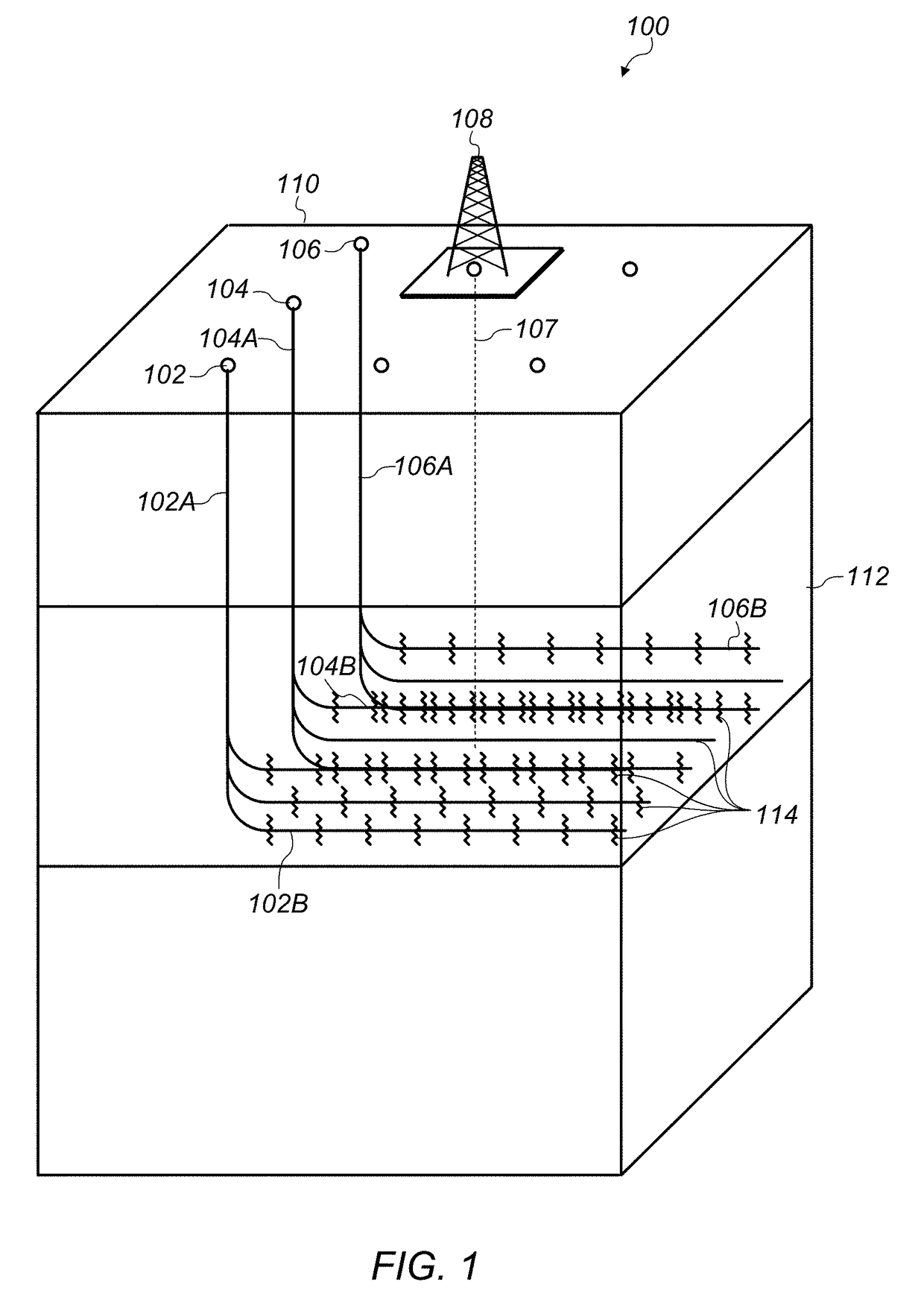
[0034]Fractures in subsurface formations as described herein are directed to fractures created hydraulically. It is to be understood, however, that fractures created by other means (such as thermally or mechanically) may also be treated using the embodiments described herein.

[0035]FIG. 1 depicts an example of an embodiment of a drilling operation on a multi-well pad. It is to be understood that the drilling operation shown in FIG. 1 is provided for exemplary purposes only and that a drilling operation suitable for the embodiments d...


PUM


Abstract

Systems and methods for assessing geometric fractures parameters in a subsurface formation are disclosed. A first pressure signal and a second pressure signal in a first (observation) wellbore in the subsurface formation may be assessed using a pressure sensor in direct fluid communication with a fluid in the first wellbore. The fluid in the first wellbore may be in direct fluid communication with at least a first fracture in the subsurface formation. The first pressure signal may include a pressure change that is induced by a second fracture being formed from a second (stimulation) wellbore in the subsurface formation. The second pressure signal may include a pressure change that is induced by a third fracture being formed from the second wellbore. One or more geometric parameters of the second and third fractures may be assessed using the first pressure signal and the second pressure signal.

Description

BACKGROUND1. Technical Field[0001]Embodiments described herein relate to systems and methods for subsurface wellbore completion and subsurface reservoir technology. More particularly, embodiments described herein relate to systems and methods for assessing geometric fracture properties in subsurface hydrocarbon-bearing formations.2. Description of Related Art[0002]Ultra-tight hydrocarbon-bearing formations (e.g., hydrocarbon-bearing resources) may have very low permeability compared to conventional resources. For example, the Bakken formation may be an ultra-tight hydrocarbon-bearing formation. These ultra-tight hydrocarbon-bearing formations are often stimulated using hydraulic fracturing techniques to enhance oil production. Long (or ultra-long) horizontal wells may be used to enhance production from these resources and provide production suitable for commercial production. However, even with these technological enhancements, these resources can be economically marginal and often ...

Claims


Application Information

Patent Timeline
Patent Type & Authority Patents(United States)
IPC IPC(8): E21B47/06E21B43/26
CPCE21B43/26E21B47/06
Inventor DAWSON, MATTHEW A.KAMPFER, GUNTHERMOSSER, LUKAS
Owner REVEAL ENERGY SERVICES INC
Why Eureka
Try Eureka