Cutting and sealing apparatuses and methods

a sealing apparatus and cutting edge technology, applied in the direction of cross-cut reciprocating saws, sawing apparatuses, paper cutting, etc., can solve the problems of cutting edges that are not prone to fraying, and the use of scissors and other conventional cutting apparatuses cannot prevent fraying. , to achieve the effect of reducing or eliminating the likelihood of misalignmen

Inactive Publication Date: 2019-03-12
AMERICAN CRAFTS LC
View PDF11 Cites 0 Cited by
  • Summary
  • Abstract
  • Description
  • Claims
  • Application Information

AI Technical Summary

Benefits of technology

[0005]In various embodiments, a cutting apparatus may be configured to hold an elongate element, such as a ribbon, in a desired orientation as the elongate element is cut into two sections. A cutting element of such a cutting apparatus may be confined to a single orientation relative to that of the elongate element, reducing or eliminating the likelihood of misalignment between the cutting element and the elongate element immediately before the elongate element is cut. In some embodiments, the cutting apparatus, or even its cutting element, may be configured to seal the newly cut ends of the elongate element.
[0006]In a specific embodiment, the cutting apparatus includes a top and a base that are configured to be assembled with the elongate element positioned therebetween, and in a manner that holds the elongate element in a desired orientation while the cutting element of the cutting apparatus engages and cuts the elongate element. One or both of the top and the base may include features that retain the elongate element in its desired orientation (to cut the elongate element precisely as desired) and in a position that enables precise and accurate cutting of the elongate element.

Problems solved by technology

Oftentimes, manual ribbon cutting results in a crooked cut, a cut having an undesirable angle, or both.
Even though many individuals are adept at using scissors to cut ribbons and other elongate elements, the use of scissors and other conventional cutting apparatuses does not prevent fraying of the cut edges.

Method used


Image

  • Cutting and sealing apparatuses and methods
  • Cutting and sealing apparatuses and methods
  • Cutting and sealing apparatuses and methods

Examples


Embodiment Construction

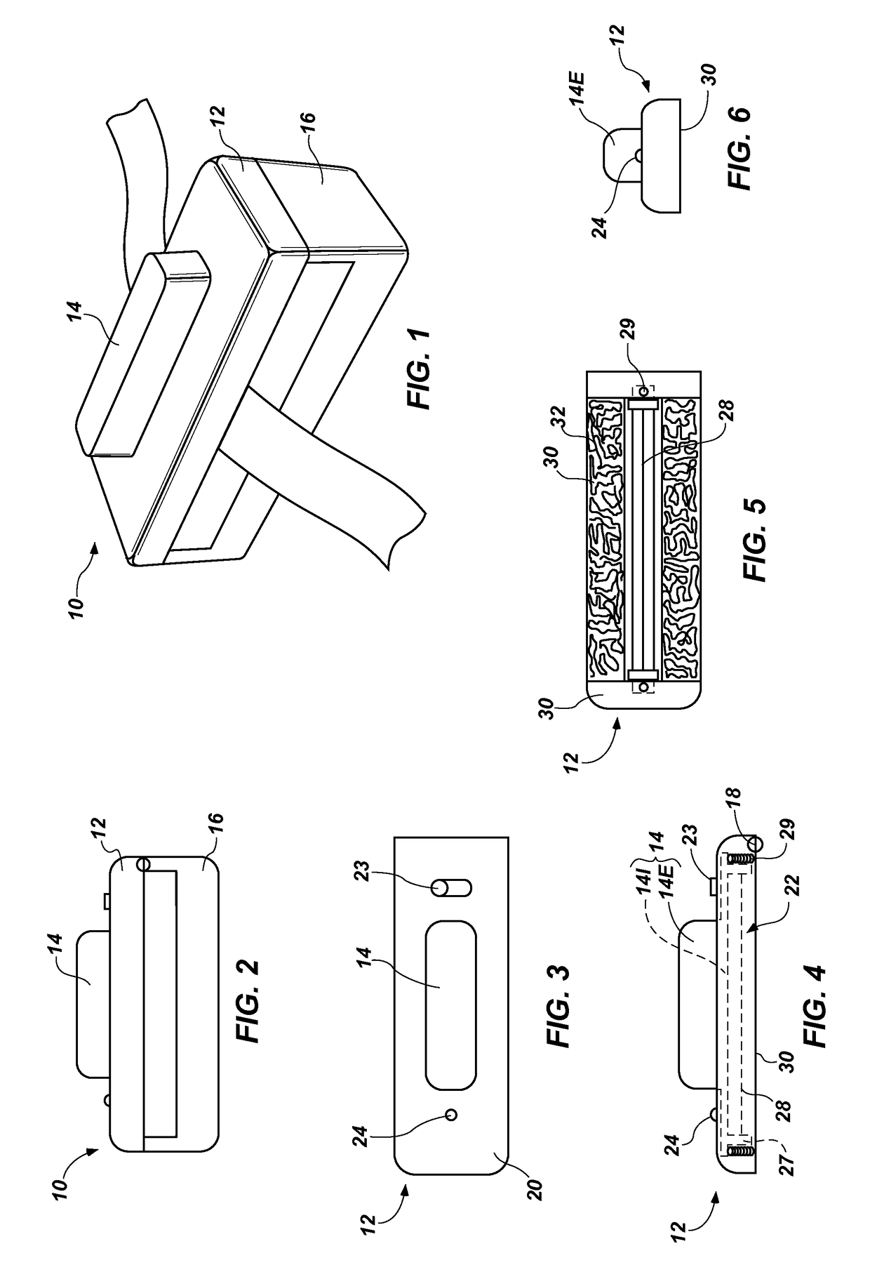
[0027]FIG. 1 illustrates an embodiment of a cutting apparatus 10 that incorporates teachings of this disclosure. The illustrated cutting apparatus 10 includes a top 12 and a base 16, which are configured to be at least partially assembled with and disassembled from one another. More specifically, the top 12 may be configured to be positioned over and assembled with the base 16 to define a closed arrangement between the top 12 and the base 16. In addition, the top 12 may be configured to be removed from or spaced apart from the base 16 to provide an open arrangement of the top 12 and the base 16. In some embodiments, a hinge 18 (FIGS. 3 and 7) may secure corresponding edges of the top 12 and the base 16 to one another to facilitate movement of the top 12 between the closed position over the base 16 and the open position relative to the base 16.

[0028]With reference to FIGS. 2 through 6, an embodiment of the top 12 of a cutting apparatus 10 is described in further detail. The top 12 ma...


PUM

PropertyMeasurementUnit
forceaaaaaaaaaa
temperatureaaaaaaaaaa
resistanceaaaaaaaaaa

Abstract

A cutting apparatus configured to hold an elongate element, such as a ribbon, in a desired orientation as the elongate element is cut into two sections. A cutting element of such a cutting apparatus may be confined to a single orientation relative to that of the elongate element, reducing or eliminating the likelihood of misalignment between the cutting element and the elongate element immediately before the elongate element is cut. In some embodiments, the cutting apparatus, or even its cutting element, may be configured to seal the newly cut ends of the elongate element. Methods for cutting and or sealing elongate elements, such as ribbons, are also disclosed.

Description

CROSS-REFERENCE TO RELATED APPLICATIONS[0001]This application is a non-provisional of U.S. Provisional Patent Application No. 61 / 506,940 titled “Portable Cutting Apparatus,” filed Jul. 12, 2011, (the “'940 Application”). A claim for the benefit of priority to the '940 Application is hereby made pursuant to 35 U.S.C. § 119(e). The entire disclosure of the foregoing application is, by this reference, hereby incorporated herein.TECHNICAL FIELD[0002]This disclosure relates generally to apparatuses for cutting elongate elements, such as ribbons, strings, cords and the like, and for sealing the cut ends of the elongate elements. More specifically, this disclosure relates to hot wire apparatus for forming clean cuts through elongate elements while sealing the cut ends of the elongate elements, and to cutting and sealing methods.BACKGROUND OF RELATED ART[0003]Conventionally, scissors have been used to cut ribbons and other elongate elements. When scissors are used to cut a ribbon, the indiv...

Claims


Application Information

Patent Timeline
Patent Type & Authority Patents(United States)
IPC IPC(8): B26D7/10B26D1/547B26F3/12D06H7/22B26D1/30
CPCB26F3/12D06H7/221B26D1/305B26D7/10Y10T83/8878Y10T83/0414Y10T83/293Y10T83/8821Y10T83/0405
Inventor DURHAM, JEFFERY S.
Owner AMERICAN CRAFTS LC
Why Eureka
Try Eureka