High reflectivity infrared coating applications for use in hirss applications

a high reflectivity, infrared coating technology, applied in the direction of machines/engines, liquid fuel engines, transportation and packaging, etc., can solve the problems of engine operating even with improved hirss systems becoming increasingly vulnerable, and achieve the effect of improving the ir performance of materials, reducing or eliminating the likelihood, and reducing the prospect of detection

Inactive Publication Date: 2009-12-24
GENERAL ELECTRIC CO
View PDF45 Cites 0 Cited by
  • Summary
  • Abstract
  • Description
  • Claims
  • Application Information

AI Technical Summary

Benefits of technology

[0019]An advantage of the present invention is that the coating improves the IR performance of the materials to which it is applied, thereby reducing or eliminating the likelihood that the material will emit infrared radiation. This, in turn, reduces the prospect of detection of the engine and hence the aircraft by IR detection devices and weapons based on IR detection.
[0020]Another advantage of the present invention is that the coating can be applied to existing HIRSS of engines so equipped and other exhaust components and immediately improve the IR performance of such engines without the need to upgrade the mechanical components of the engines. Alternatively, the coating of the present invention can be applied to any newly improved HIRSS and other exhaust components of engines, thereby increasing the temperature range over which the engine can perform with decreased likelihood of detection by IR-seeking devices.
[0021]Another advantage of the present invention is that it can readily be applied to as-manufactured engine components with little preparation, except for cleaning. The coating of the present invention can conveniently be applied by spraying, although other methods such as brushing or dipping can also be used.
[0022]Still another advantage of the present invention is that the material applied to the HIRSS and other components of the exhaust system is readily repairable if it should be subject to foreign object damage (FOD) or damage as a result of use over time. Repair can be readily accomplished in the field. Repair using the present invention requires reprocessing the component through a fire cycle.

Problems solved by technology

While these improvements have been effective in suppressing infrared radiation, the continued increase in engine operating temperature as well as improvements in detection by advances in threat systems have made engines operating even with improved HIRSS systems increasingly vulnerable.

Method used


Image

  • High reflectivity infrared coating applications for use in hirss applications
  • High reflectivity infrared coating applications for use in hirss applications
  • High reflectivity infrared coating applications for use in hirss applications

Examples


Embodiment Construction

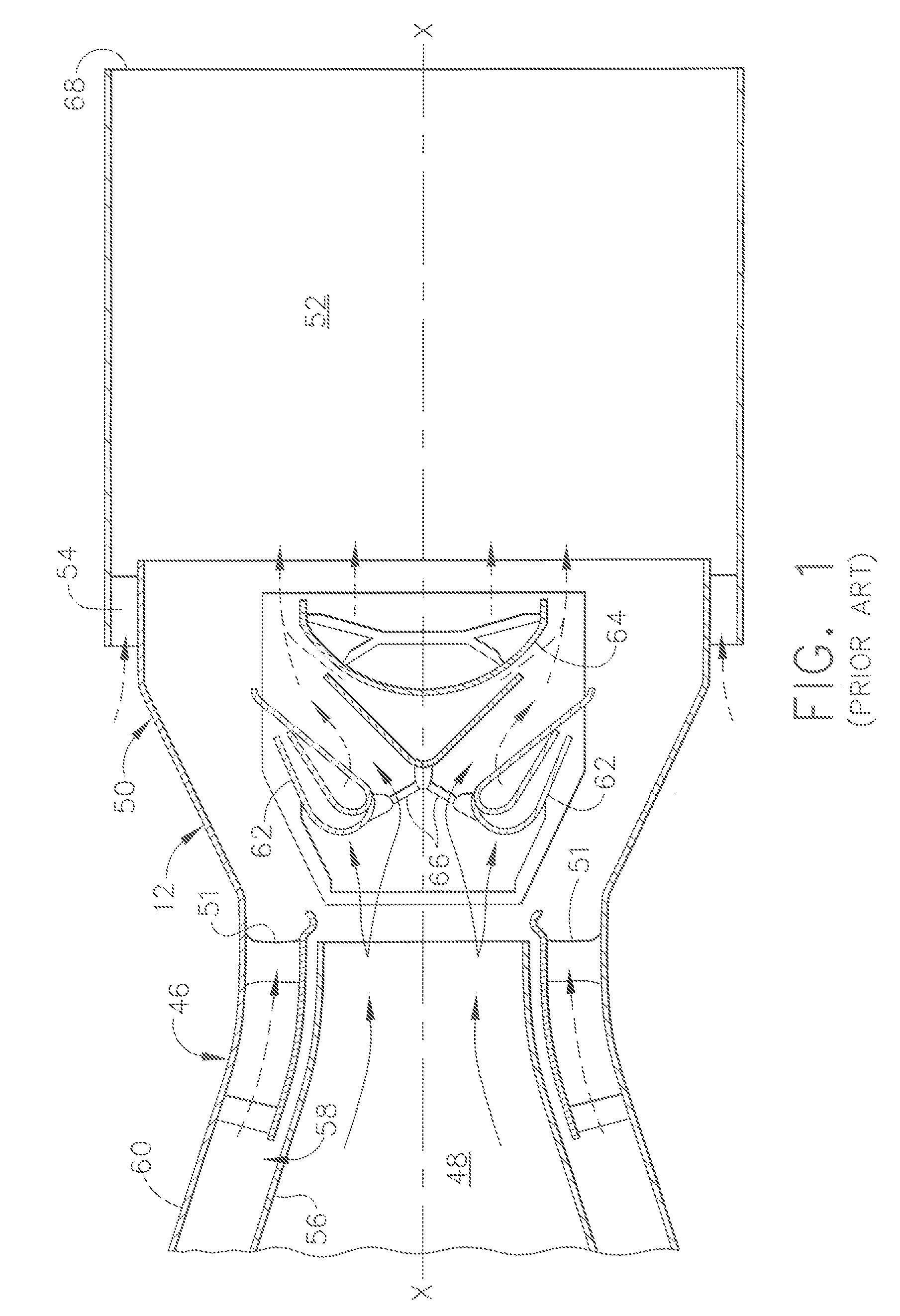
[0035]The present invention is directed for use a gas turbine engine of the conventional turboshaft type, but its use is not so limited, and it may be used with other types of gas turbine engines such as turbofan and turboprop engines. FIG. 1 depicts a cross-sectional schematic view of a prior art infrared suppression system for use in a gas turbine engine of the conventional turboshaft type, such as the GE T-700, wherein the power turbine shaft may be connected to drive rotor blades of a helicopter. This prior art infrared suppression system utilizes a mechanical arrangement of baffles to achieve the improvement in IR performance to mix hot and cool gases while eliminating line of sight IR so as to improve engine performance. The system achieves its improved IR performance without the use of Low-E materials. While the system provided an acceptable solution for its time, the current infirmities with the system are discussed above. FIG. 1 is set forth fully in U.S. Pat. No. 6,253,540...


PUM

PropertyMeasurementUnit
weight percentaaaaaaaaaa

Abstract

The present invention is a hover infrared suppression system for a gas turbine engine comprising a hover infrared suppression system having an upstream first stage, a second stage downstream of the first stage and a third stage downstream of the second stage, the engine operating at a temperature sufficient to cause the hover infrared suppression system to emit infrared radiation. The present invention further comprises a high reflectivity coating applied over a preselected area of at least one of the stages of the hover infrared suppression system to reduce the infrared radiation emitted from the engine, the high reflectivity coating being fired after application.

Description

CROSS-REFERENCE TO RELATED APPLICATIONS[0001]This application is related to U.S. Pat. No. 6,720,034 B2, issued on Apr. 13, 2004, entitled “METHOD OF APPLYING A METALLIC HEAT REJECTION COATING ONTO A GAS TURBINE ENGINE COMPONENT,” assigned to the assignee of the present invention and which is incorporated herein by reference in its entirety and U.S. application Ser. No. 10 / 726,361, Attorney Docket No. 13DV-13637, filed on Dec. 3, 2003, entitled “SPRAYABLE NOBLE METAL COATING FOR HIGH TEMPERATURE USE DIRECTLY ON AIRCRAFT ENGINE ALLOYS,” assigned to the assignee of the present invention and which is incorporated herein by reference in its entirety.FIELD OF THE INVENTION[0002]The present invention is directed to a low emissivity, or high reflectivity, coating for use in HIRSS applications, and specifically to the use of the low emissivity, or high reflectivity, coatings for use in T-700 helicopter engines employing HIRSS hardware.BACKGROUND OF THE INVENTION[0003]Hover Infrared Suppressi...

Claims


Application Information

Patent Timeline
Patent Type & Authority Applications(United States)
IPC IPC(8): F02C7/24
CPCB32B15/018C22C19/055C23C24/08C23C26/00C23C30/00Y10T428/12861F05D2300/611F05D2230/90Y10T428/12875Y10T428/12771Y10T428/12806F02K1/825
Inventor SKOOG, ANDREW JAYMURPHY, JANE ANNJASANY, JOHN MICHAELSENTER, MARIAH DAWN
Owner GENERAL ELECTRIC CO
Why Eureka
Try Eureka