LED module sealing technology

a technology of led modules and sealing processes, applied in the direction of lighting and heating apparatus, semiconductor devices for light sources, coupling device connections, etc., can solve the problems of short service life, easy scratching and damage of film, and easy breakage of led products during use, so as to prevent moisture intrusion, reduce the amount of glue and the product weight, and prolong the service life

Active Publication Date: 2019-03-26
HANGZHOU HPWINNER OPTO CORP
View PDF8 Cites 0 Cited by
  • Summary
  • Abstract
  • Description
  • Claims
  • Application Information

AI Technical Summary

Benefits of technology

[0017]Preferably, the external-threaded nut is hollow so that the waterproof wire and the sealing ring can go through from its center. There is a thread structure on the internal wall of the through hole and the thread structure matches with the nut. The wedge part in one side of the sealing ring is installed in the gap between the through hole and the waterproof wire, and the wedge part in the other side is press-stalled tightly when the nut is screwed, making the through-hole, the sealing ring, the waterproof wire and the external-threaded nut fit closely by the deformation caused by the sealing ring being pressed in the above process, thus achieving the waterproof effect.
[0045]Good sealing effect is achieved by this simple process, rendering lower cost, longer service life, no damage to products itself and higher production efficiency: the sealing process of the product reduces the cost, meanwhile achieve good sealing effect, achieving waterproofing, damp proofing, corrosion protection and oxidation protection, thus prolonging the service life and improving the safety of LED lighting products.

Problems solved by technology

LED products may break down during its usage due to the penetration of moisture or other harmful gases into the base plate or metal oxidation.
Traditional LED products, with the waterproof structure of box-packaged and screws-tightened, are usually heavy and thick, which have great influence to the heat dissipation performance.
The disadvantages of it include that the film can be easily scratched and damaged, rendering short service life.
Meanwhile, complete coverage of thin film on the entire lamp means harder craft and higher cost.

Method used


Image

  • LED module sealing technology
  • LED module sealing technology
  • LED module sealing technology

Examples


embodiment 1

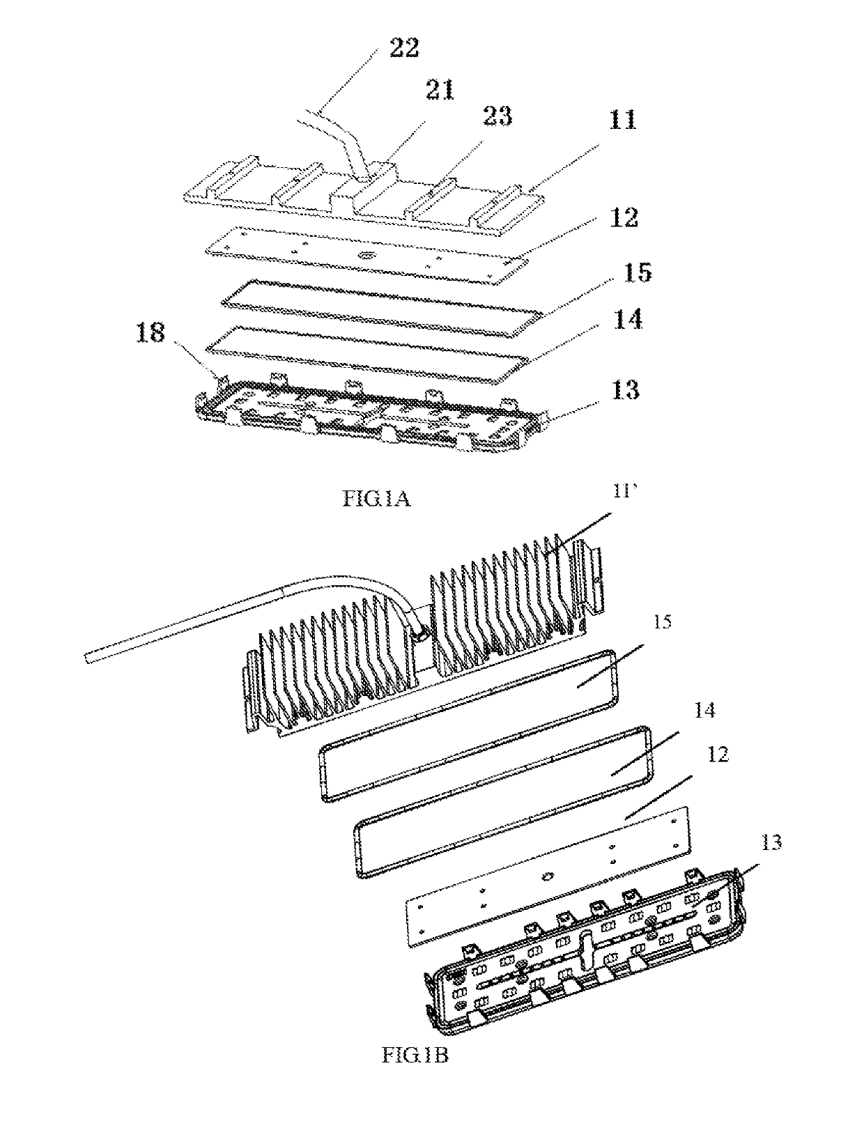
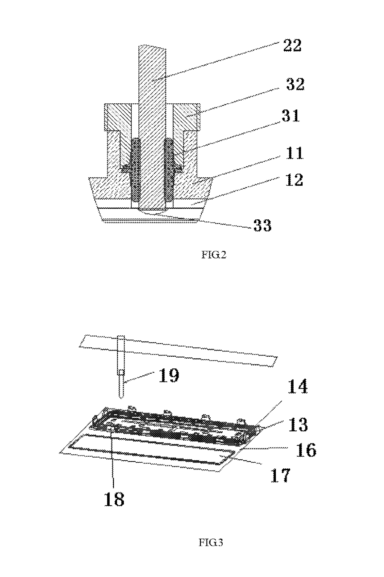
[0067]With reference to FIGS. 1-3, it is a type of technical proposal for LED sealing process: an LED lighting device including a heat sink 11 (in the present invention, heat sink is same with radiation holder. To avoid any confusion, hereby radiation holder is referred to as heat sink), a PCB board 12, a LED chip, a sealing silica gel and lens set 13. The LED chip is welded on the PCB board 12, and the PCB board 12 is fit with the heat sink 11. The lens set 13 is set above the LED chip.

[0068]The heat sink can include one lamp holder unit or several lamp holder units. Each lamp holder unit corresponds to one PCB board 12, one lens set 13 and sealing silica gel. Hereinafter single lamp holder unit is adopted as an example:

[0069]The heat sink 11 could be cut from a profile, functioning both as lamp holder and heat sink. The processing is simple and lower cost. Profile of different shapes for the heat sink can be adopted based on different demands.

[0070]On the heat sink 11, a through h...

embodiment 2

[0115]Processing steps of Embodiment 2 are similar to that of Embodiment 1, and the differences are as following: set the solid silica gel ring in the external groove of the lens set, and then paste a circle of liquid silica gel evenly along the internal groove of the lens set. For other processing steps, please refer to Embodiment 1.

embodiment 3

[0116]Only one groove is set on the periphery of the lens set; one of the sealing ring and the liquid silica gel is set on the groove, and the other is set inside or on the periphery of the groove.


PUM


Abstract

A sealing process of LED modules, comprising: (1) a waterproof wire goes through a wire-through hole of a heat sink to be connected with a positive-negative solder joints on a PCB board, wherein the positive-negative solder joint and the position that the waterproof wire going through are subjected to glue sealing treatment, and a waterproof sealing process is operated between the waterproof wire and the wire-through hole; (2) fix the PCB board on the heat sink; (3) place one sealing ring into one of the grooves; (4) apply evenly a ring of liquid silica gel along the other groove of the lens set and the amount of the liquid silica gel is limited to completely sticking the solid silica gel sealing ring; (5) the heat sink installed with the PCB board and the waterproof wire as processed in step (2) is inversely buckled on the lens set which is set with the solid silica gel ring and the liquid silica gel as processed in step (4), so as to fix the heat sink entirety and the lens set. At least two waterproof sealing rings are used for completely isolating an LED chip from the outside so as to prevent all water vapor or other harmful gases from corroding the chip and the PCB, and the sealing rings are firmer when being compared with thin film sealing; the service life is longer and the guarantees to the sealing performance between the lens set and the heat radiation frame are realized.

Description

CROSS-REFERENCE TO RELATED APPLICATIONS[0001]This application is a Continuation-in-Part of co-pending application Ser. No. 14 / 403,108 filed on Nov. 21, 2014, which is a U.S. National Stage of International Application No. PCT / CN2013 / 076937 filed on Jun. 7, 2013, for which priority is claimed under 35 U.S.C. § 120; and this application claims priority of Application Nos. 201210188159.1 filed in China on Jun. 8, 2012, 201320278363.2 filed in China on May 21, 2013, and 201310189101.3 filed in China on May 21, 2013 under 35 U.S.C. § 119; the entire contents of all of which are hereby incorporated by reference.TECHNICAL FIELD[0002]The present invention relates to LED lighting device, especially to a sealing process for an LED module.BACKGROUND ART[0003]In the trend that energy conservation and environmental protection are promoted, LED has been applied more and more widely due to its feature of energy conservation and environmental protection, long service life, fast start-up, good safet...

Claims


Application Information

Patent Timeline
Patent Type & Authority Patents(United States)
IPC IPC(8): H01R4/56H01R12/53H02G15/013H01R13/52H01R13/58H02G3/22F21V27/02F21V31/00F21Y115/10
CPCH02G15/013F21V27/02F21V31/005H01R4/56H01R13/5205H01R13/5804H02G3/22H01R12/53F21Y2115/10
Inventor CHEN, KAIHUANG, JIANMINGLU, HUALI
Owner HANGZHOU HPWINNER OPTO CORP
Why Eureka
Try Eureka