Pneumatic tire

a technology of pneumatic tires and treads, applied in the field of pneumatic tires, can solve problems such as insatiable drainage, and achieve the effects of improving drainage, and reducing the number of tyre treads

Inactive Publication Date: 2019-04-09
BRIDGESTONE CORP
View PDF29 Cites 0 Cited by
  • Summary
  • Abstract
  • Description
  • Claims
  • Application Information

AI Technical Summary

Benefits of technology

[0023]As described hereabove, because the pneumatic tire recited in the first aspect has the described structure, drainage may be improved while stiffness at the vehicle outer side when the tire is mounted at a vehicle is assured.
[0024]Because the tire recited in the second aspect has the described structure, stiffness of the land portion adjacent to the vehicle outer side, when the tire is mounted at the vehicle, of the outermost side circumference direction main groove may be assured.
[0025]Because the tire recited in the third aspect has the described structure, stiffness at the acute corner side may be raised, a difference in stiffness between the corner portions may be moderated, and uneven wear may be suppressed.
[0026]Because the tire recited in the fourth aspect has the described structure, drainage may be further improved.
[0027]Because the tire recited in the fifth aspect has the described structure, water captured at the outer side rib side may be drained using both the shoulder circumference direction narrow groove and the outermost side circumference direction main groove, and the water may be drained efficiently.

Problems solved by technology

However, drainage cannot be considered satisfactory from just the formation of narrow circumference direction grooves, and technologies to further improve drainage are being called for.

Method used


Image

  • Pneumatic tire
  • Pneumatic tire
  • Pneumatic tire

Examples


Embodiment Construction

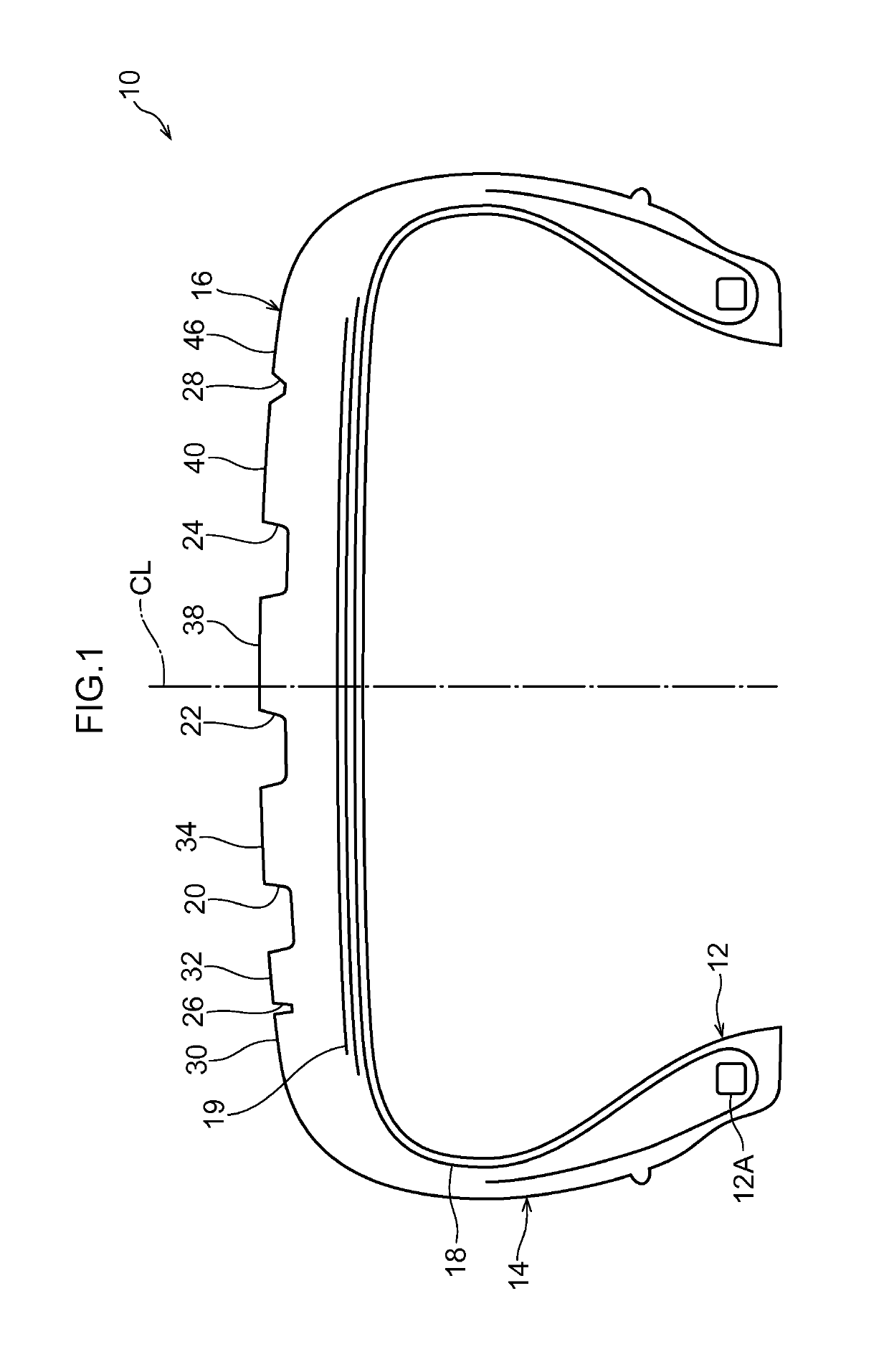
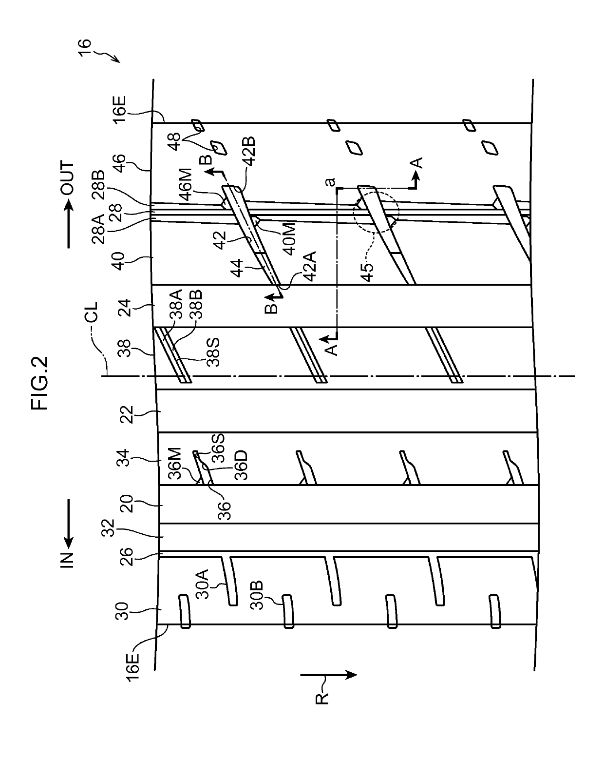
[0037]Herebelow, a pneumatic tire 10 in accordance with a first exemplary embodiment of the present invention is described in accordance with the attached drawings. In the drawings, the arrow IN indicates an inner side (hereinafter referred to as “the tire mounting inner side”) when the tire is mounted at a vehicle (hereinafter referred to with the term “when the tire is mounted”), and an arrow OUT indicates the outer side when the tire is mounted (hereinafter referred to as “the tire mounting outer side”). The single-dot chain line CL indicates the equatorial plane of the tire.

[0038]As shown in FIG. 1, the pneumatic tire 10 according to the present exemplary embodiment includes a pair of bead portions 12, a pair of sidewall portions 14 and a tread portion 16. At least one annular bead core 12A is embedded at each bead portion 12. A carcass 18 is provided so as to extend in a toroidal shape between the pair of bead cores 12A. At each bead core 12A, the carcass 18 is folded back from...


PUM


Abstract

An outer side rib 46 is formed at a side relative to the plural circumference direction main grooves that is at the vehicle outer side when the tire is mounted at a vehicle. A land portion of the outer side rib 46 is continuous in the tire circumference direction. Of the plural circumference direction main grooves, an outermost side circumference direction main groove 24 is formed at the vehicle outermost side when the tire is mounted. Fourth lug grooves 42 extend from the outermost side circumference direction main groove 24 toward the outer side rib 46. The groove width of each fourth lug groove 42 widens from the outermost side circumference direction main groove 24 side toward the outer side rib 46 side. The fourth lug grooves 42 terminate at the outermost side circumference direction main groove 24 side relative to a tire ground contact edge 16E.

Description

CROSS REFERENCE TO RELATED APPLICATIONS[0001]This application is a National Stage of International Application No. PCT / 2012 / 083344 filed Dec. 21, 2012, claiming priority based on Japanese Patent Application Nos. 2011-286672 filed Dec. 27, 2011 and 2011-286674 filed Dec. 27, 2011, the contents of all of which are incorporated herein by reference in their entirety.TECHNICAL FIELD[0002]The present invention relates to a pneumatic tire, and particularly relates to a pneumatic tire featuring a tread pattern that is formed plurally in the tire circumference direction.BACKGROUND ART[0003]In general, at a pneumatic tire at a time of cornering, a ground contact pressure of the pneumatic tire is higher at the vehicle outer side than at the vehicle inner side. Therefore, to improve cornering characteristics, an increase in tread stiffness at a tire mounting outer side is called for. Meanwhile, it is also necessary to consider drainage characteristics during running on wet road surfaces. Accord...

Claims


Application Information

Patent Timeline
Patent Type & Authority Patents(United States)
IPC IPC(8): B60C11/03B60C11/13B60C11/01B60C11/12B60C11/04
CPCB60C11/0304B60C11/01B60C11/042B60C11/1236B60C11/13B60C2011/0393B60C2011/0351B60C2011/0367B60C2011/0369B60C2011/0381B60C2011/0388B60C2011/0348
Inventor NAKAMURA, TAKAMITSUKAWAHARA, TAKAHIRO
Owner BRIDGESTONE CORP
Why Eureka
Try Eureka