Method for producing forged crankshaft

a crankshaft and forging technology, applied in the direction of crankshafts, mechanical equipment, rotary machine parts, etc., can solve the problems of flash formation, difficult to produce such a forged crankshaft with such uniquely shaped arms by a conventional production method, and the inability to remove the forged blank from the die, so as to improve the thickness of the side portion, reduce weight, and ensure the effect of stiffness

Active Publication Date: 2019-09-17
NIPPON STEEL CORP
View PDF10 Cites 0 Cited by
  • Summary
  • Abstract
  • Description
  • Claims
  • Application Information

AI Technical Summary

Benefits of technology

[0031]In the forged crankshaft production method according to the present invention, in the rough forging step, at least one of the rough crank arms is formed to have, in a region near an adjacent rough pin, an excess portion protruding from an outer periphery of a side of the rough crank arm. In the finish forging step, the excess portion is deformed by a pair of dies to bulge toward an adjacent rough journal. This allows formation of a recess in the journal-facing surface of the arm and an increase in the thickness of the side portion of the arm in the region near the adjacent pin. Accordingly, the forged crankshaft produced by this method has a reduced weight and assured stiffness. Since the excess portion is deformed by die forging in the finish forging step, the deformation can be carried out in a simple manner by use of an existing equipment.

Problems solved by technology

During the rough forging and the finish forging, excess material flows out through a space between the mutually facing parting faces of the dies, which results in formation of flash.
It is, however, difficult to produce such a forged crankshaft with such uniquely shaped arms by a conventional production method.
When a recess is to be formed in the surface of an arm in the die forging step, the draft of the die will become a reverse draft at the site of the recess, and therefore, the forged blank will not be able to be removed from the die.

Method used


Image

  • Method for producing forged crankshaft
  • Method for producing forged crankshaft
  • Method for producing forged crankshaft

Examples


Embodiment Construction

[0064]An embodiment of the present invention will hereinafter be described. However, the present invention is not limited to the embodiment to be described below.

(Forged Crankshaft Production Method)

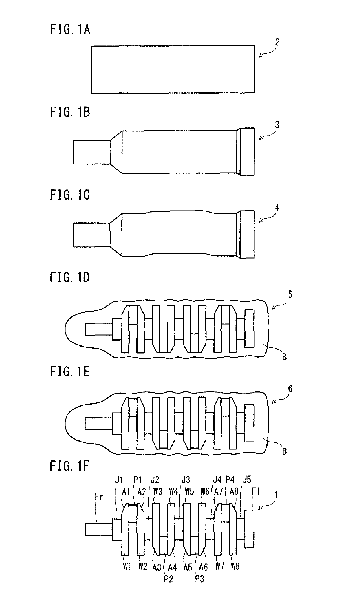
[0065]A production method according to the present invention is a method for producing a forged crankshaft. The forged crankshaft includes journals serving as a center of rotation, pins decentered from the journals, and crank arms connecting the journals to the pins. The forged crankshaft further includes counterweights integrated with all or some of the crank arms.

[0066]The production method according to the present invention includes a rough forging step and a finish forging step to be executed in this order. The rough forging step is to obtain a rough forged blank with flash formed in a crankshaft shape by die forging. The rough forged blank has roughly the same shape as the crankshaft. The rough forged blank includes rough journals, rough pins, rough crank arms and rough counterweigh...


PUM

PropertyMeasurementUnit
poweraaaaaaaaaa
strengthaaaaaaaaaa
stiffnessaaaaaaaaaa

Abstract

The disclosed production method includes a rough forging step of performing die forging to obtain a rough forged blank with flash having a crankshaft shape, and a finish forging step of applying die forging by use of a first pair of dies to the rough forged blank to obtain a finish forged blank with flash. In the rough forged blank, at least one of the rough crank arms have, in a region near an adjacent rough pin, a first excess portion protruding from an outer periphery of a side portion of the rough crank arm. During the die forging in the finish forging step, the first excess portion is deformed by the first pair of dies to bulge toward an adjacent rough journal.

Description

TECHNICAL FIELD[0001]The present invention relates to a method for producing a crankshaft by forging and more particularly to a method for producing a crankshaft by hot forging.BACKGROUND ART[0002]A reciprocating engine to be employed in a motor vehicle, a motorcycle, an agricultural machine, a marine vessel or the like requires a crankshaft to extract power by converting reciprocating motions of pistons to rotational motion. There are two types of crankshafts: the type manufactured by die forging and the type manufactured by casting. Especially when high strength and high stiffness are required, forged crankshafts manufactured by die forging are often employed.[0003]A forged crankshaft is generally produced by using a billet as a starting material. The billet is circular or square in cross section, and the cross-sectional area is constant throughout the length. A method for producing a forged crankshaft includes a preforming step, a die forging step, and a trimming step that are to...

Claims


Application Information

Patent Timeline
Patent Type & Authority Patents(United States)
IPC IPC(8): B21K1/08B21J5/02F16C3/08F16F15/26
CPCF16C3/08B21K1/08B21J5/027F16C2220/46F16F15/26
Inventor TAKAMOTO, SHOTAMURA, KENJIYAMASHITA, TOMOHISAYABUNO, KUNIHIROYOSHINO, KENKUROKAWA, HIROYUKIOKUBO, JUNICHIISHIHARA, KOICHIRO
Owner NIPPON STEEL CORP
Why Eureka
Try Eureka