Driving force transmission mechanism and image forming apparatus

a transmission mechanism and driving force technology, applied in the direction of gearing elements, belts/chains/gearrings, hoisting equipments, etc., can solve the problems of driving force transmission loss, inability to reduce the driving force transmission loss attributable to loss of driving force transmission

Active Publication Date: 2019-04-09
CANON KK
View PDF16 Cites 0 Cited by
  • Summary
  • Abstract
  • Description
  • Claims
  • Application Information

AI Technical Summary

Benefits of technology

[0004]Thus, the primary object of the present invention is to provide such a driving force transmission mechanism that is significantly smaller in the driving force transmission loss attributable to the thrust load than any of conventional driving force transmission mechanisms.

Problems solved by technology

However, the application of lubricant causes driving force transmission loss attributable to the phenomenon that lubricant increases in viscosity as the ambient temperature falls.
However, conventional driving force transmission mechanism such as the above-described one suffer from the problem that they cannot reduce the driving force transmission loss attributable to the thrust load.

Method used


Image

  • Driving force transmission mechanism and image forming apparatus
  • Driving force transmission mechanism and image forming apparatus
  • Driving force transmission mechanism and image forming apparatus

Examples


embodiment 1

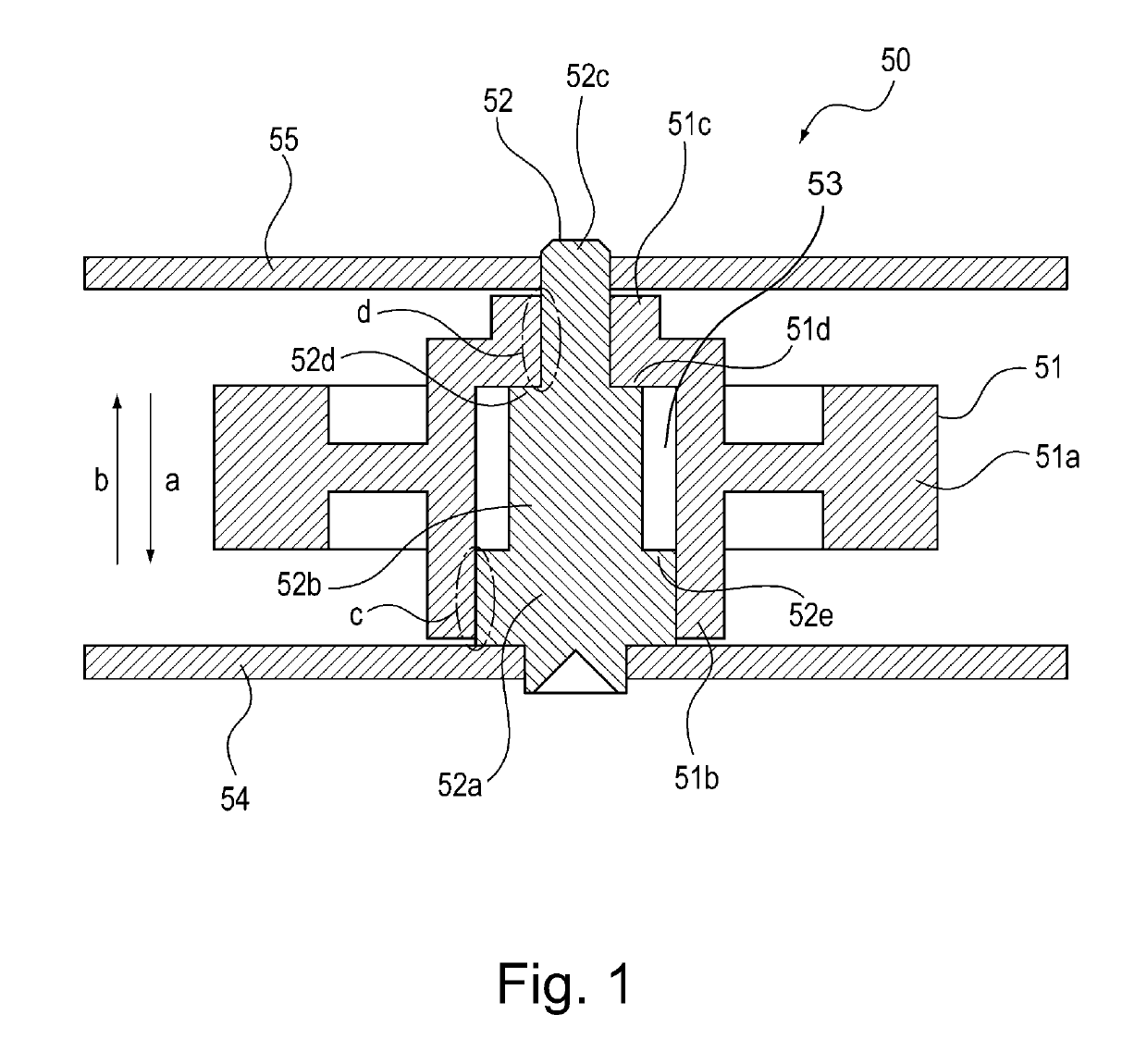
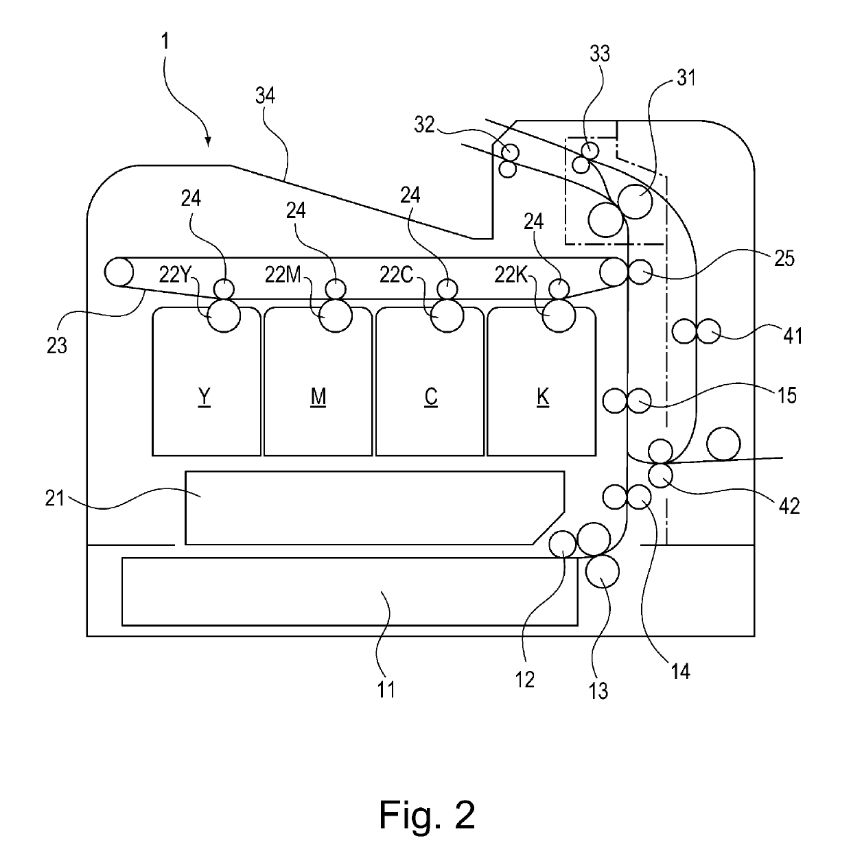
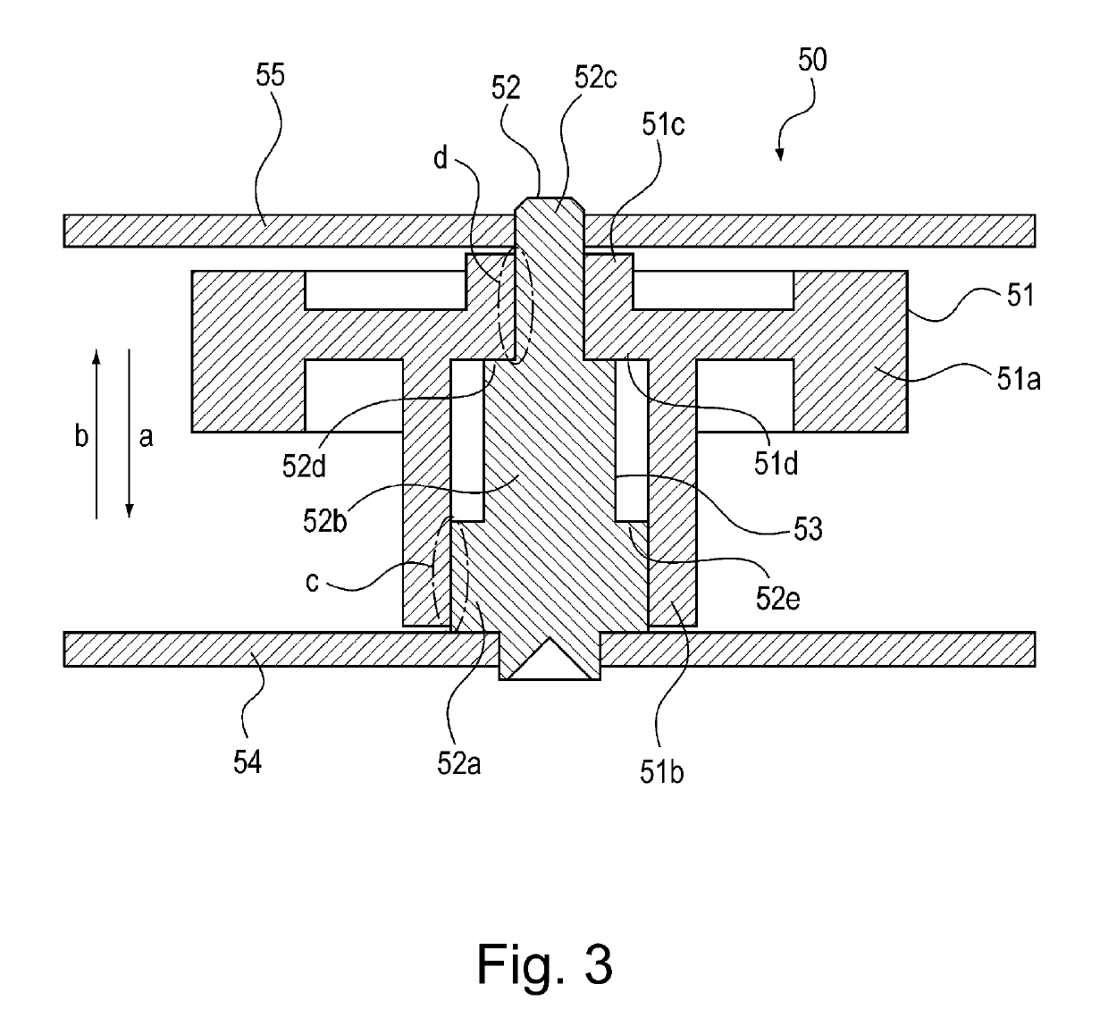
[0017]Next, the first embodiment of the present invention is described with reference to FIGS. 1-6. FIG. 1 is a sectional view of the driving force transmission mechanism in the first embodiment, and FIG. 2 is a sectional view of the image forming apparatus equipped with the driving force transmission mechanism, in the first embodiment. It shows the general structure of the apparatus. FIGS. 3-6 are sectional views of modified versions of the driving force transmission mechanisms, one for one, in the first embodiment.

[0018]To begin with, referring to FIG. 2, the overall structure of the image forming apparatus equipped with a driving force transmission mechanism is roughly described. The image forming apparatus 1 shown in FIG. 2 is structured, as a color laser printer, so that a cassette 11 in which sheets of recording medium are storable in layers can be removably installed in the bottom portion of the main assembly of the image forming apparatus 1. The sheets of recording medium in...

embodiment 2

[0043]Next, referring to FIG. 7, the second embodiment of the present invention is described. FIG. 7 is a sectional view of the driving force transmission mechanism 60 in the second embodiment.

[0044]The driving force transmission mechanism 60 shown in FIG. 7 is made up of a gear 61, a shaft 62 by which the gear 61 is rotatably supported, a side plate 64 which is integral with the shaft 62, and a side plate 65 which functions as a component to prevent the gear 61 from becoming disengaged.

[0045]The gear 61 is molded of a substance such as polyacetal which is excellent in that a component formed of it is low in surface friction. It is made up of a driving force transmitting section 61a, a large internal diameter section 61b by which it is supported by the shaft 62, a small internal diameter section 61c by which it is supported by the shaft 62, and an internal step section 61d which is between the inward surface of the large internal diameter section 61b and small internal diameter sect...


PUM


Abstract

A drive transmission mechanism includes a rotatable member provided with a drive transmitting portion; and a shaft supporting the rotatable member; wherein the shaft has a large diameter portion, a small diameter portion having a diameter smaller than that of the large diameter portion, at least one middle diameter portion having a diameter smaller than that of the large diameter portion and larger than that of the small diameter portion, and a stepped portion at a boundary between the small diameter portion and the middle diameter portion.

Description

FIELD OF THE INVENTION AND RELATED ART[0001]The present invention relates to a driving force transmission mechanism having gears, etc., and an image forming apparatus equipped with the above described driving force transmission mechanism.[0002]Rotational members having a driving force transmitting section comprising gears, etc., have been used as a driving force transmission mechanism in various fields. They have been known to have such a structure that a gear 121 is rotatably fitted around a straight shaft 122, being thereby supported by the shaft 122, as shown in FIG. 8. In recent years, in response to the increased desire to reduce an image forming apparatus in electric power consumption, it has come to be desired to reduce a driving force transmission mechanism such as the above-described one in the amount of driving force transmission loss attributable to rotational members such as gears. Some of the causes of the driving force transmission loss, which occurs to driving force t...

Claims


Application Information

Patent Timeline
Patent Type & Authority Patents(United States)
IPC IPC(8): F16H55/17F16H57/00
CPCF16H55/17F16H57/0031
Inventor TSUKAHARA, TAKESHIMATSUBARA, HIDEYUKI
Owner CANON KK
Why Eureka
Try Eureka