Pre-tensioning mechanism

a technology of pretensioning mechanism and piston rod, which is applied in the direction of vehicle safety belts, belt retractors, vehicle components, etc., can solve the problems of loss of force transmitted from the piston rod to the toothed ratchet, and achieve the effect of convenient disassembly

Active Publication Date: 2016-06-21
KK TOKAI RIKA DENKI SEISAKUSHO
View PDF11 Cites 0 Cited by
  • Summary
  • Abstract
  • Description
  • Claims
  • Application Information

AI Technical Summary

Benefits of technology

[0007]In consideration of the above circumstances, the present invention provides a pre-tensioning mechanism that enables the loss in a force transmitted from a moving member to a rotating member to be reduced.
[0015]Configuration is made such that the hardness of the moving tooth is different from that of the rotating tooth and at least one of the moving tooth or the rotating tooth is deformable (“deformable” including “broken”) when firstly the moving tooth engages with the rotating tooth. Thus the deformation of at least one of the moving tooth or the rotating tooth enables the sticking-in of the moving tooth and the rotating tooth to be suppressed, or the sticking-in of the moving tooth and the rotating tooth to be easily eliminated, thereby enabling the loss in the force transmitted from the moving member to the rotating member to be reduced.
[0017]In the pre-tensioning mechanism of the third aspect, the portion of one of the moving tooth or the rotating tooth is engaged with the other of the moving tooth or the rotating tooth when initial engaging of the moving tooth with the rotating tooth. Therefore, one of the moving tooth or the rotating tooth is easily deformed, thereby enabling the sticking-in of the moving tooth and the rotating tooth to be effectively suppressed or the sticking-in between the moving tooth and rotating tooth to be eliminated more easily.
[0018]In the pre-tensioning mechanism of the fourth aspect, the moving tooth is displaced towards the rotating tooth side by the engagement of the moving tooth with the rotating tooth, increasing the amount of engagement between one of the moving tooth or the rotating tooth with the other. Thus more effective transmission of the force from the moving member to the rotating member is enabled, even though at least one of the moving tooth or the rotating tooth is deformed when the moving tooth initially engage with the rotating tooth.
[0021]Moreover, the circular arc shaped cross-section outer peripheral face of the moving member is disposed at the circular arc shaped cross-section inner peripheral face of the guide member. Therefore, due to the moving tooth engaging with the rotating tooth portion, the moving member is capable of rotating in a circumferential movement direction whilst being guided by the guide member and the moving tooth is easily displaced to the rotating tooth side.

Problems solved by technology

This consequently gives rise to the possibility of a loss in a force transmitted from the piston rod to the toothed ratchet.

Method used


Image

  • Pre-tensioning mechanism
  • Pre-tensioning mechanism
  • Pre-tensioning mechanism

Examples


first exemplary embodiment

[0033

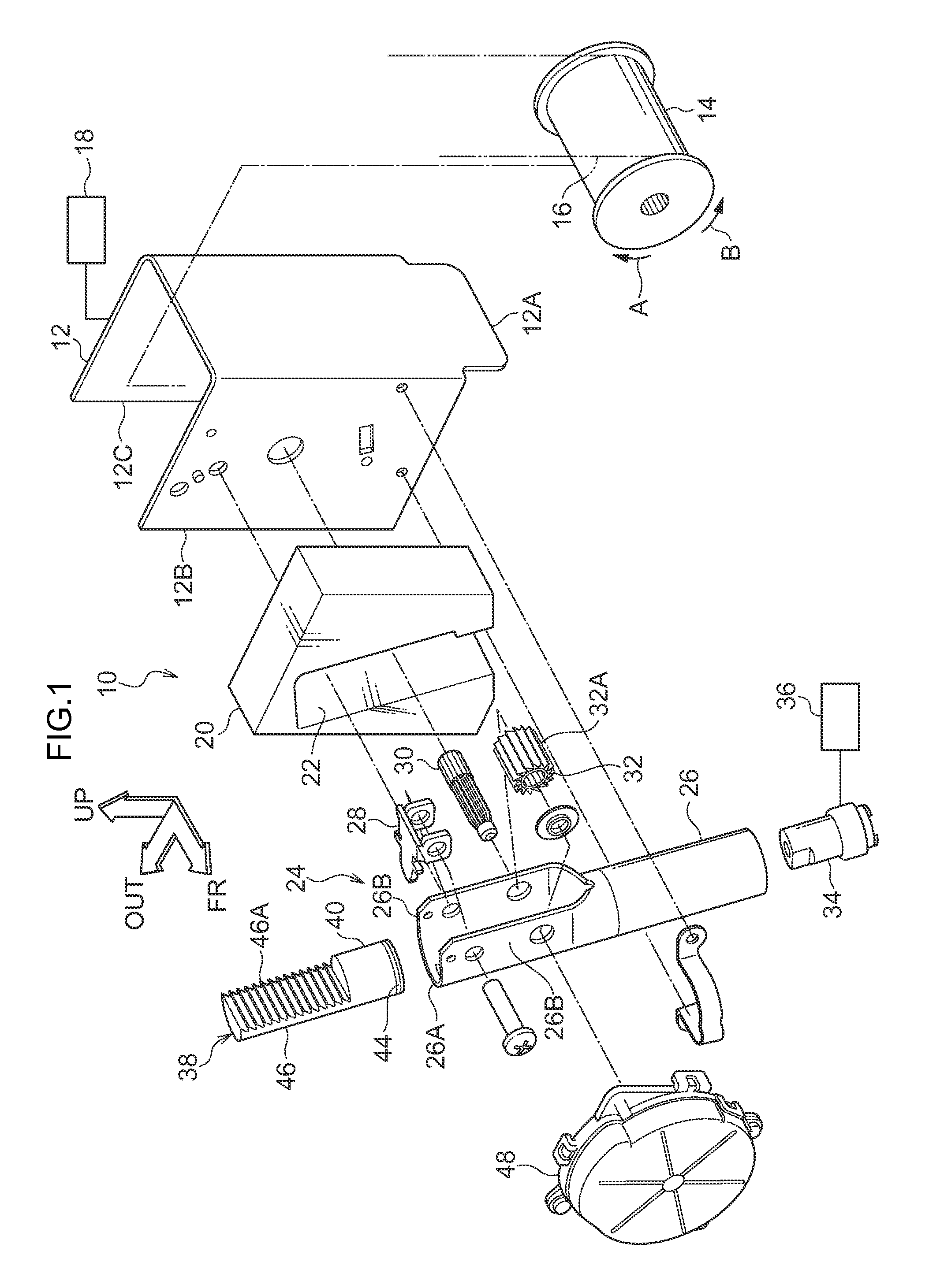
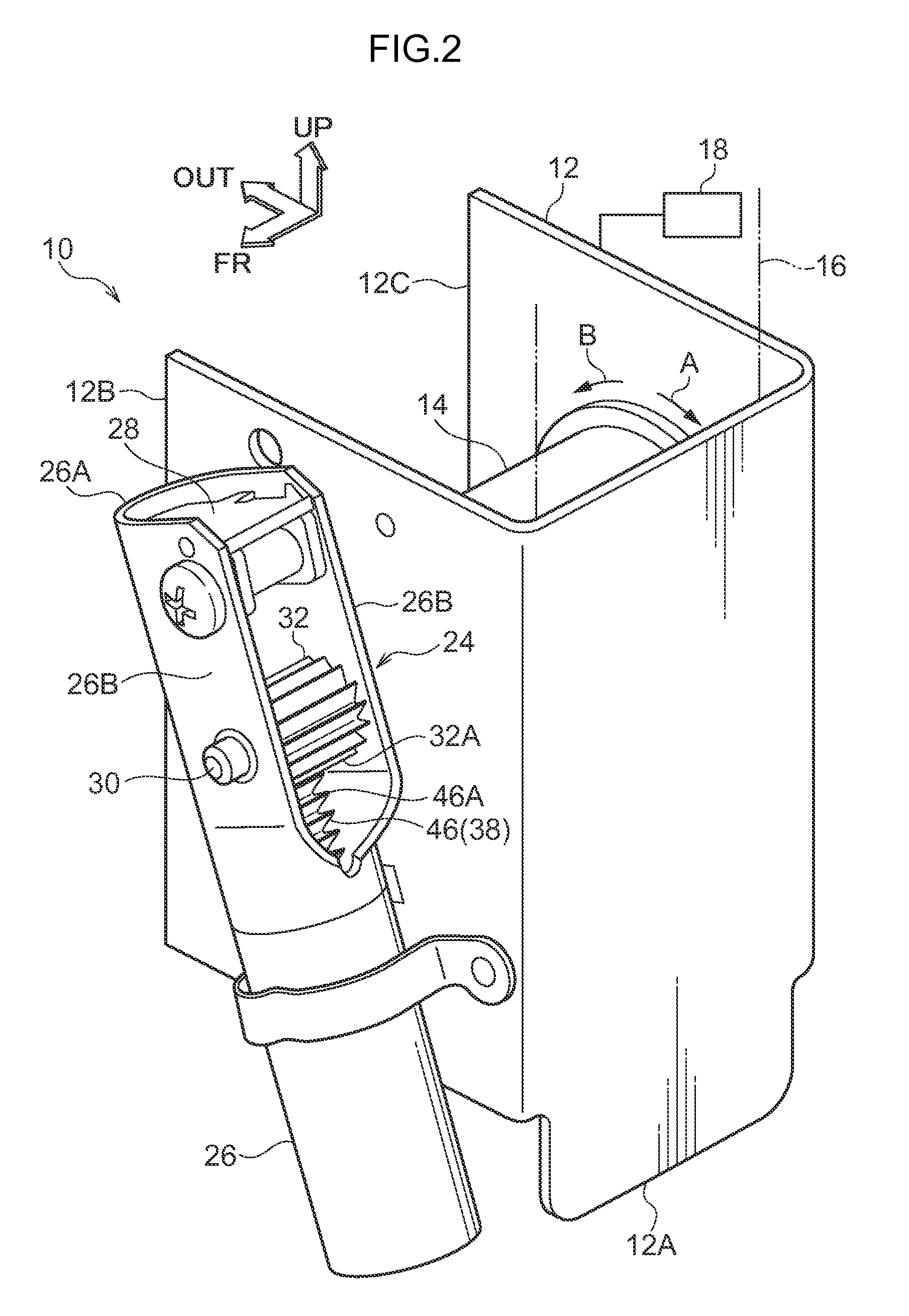
[0034]FIG. 1 is an exploded perspective view illustrating a webbing take-up device 10 applied with a pre-tensioning mechanism 24 of a first exemplary embodiment of the present invention. FIG. 2 is a perspective view illustrating the webbing take-up device 10. Note that in that figures the arrow OUT indicates a vehicle width direction outside, the arrow FR indicates one side in the vehicle front-rear direction and the arrow UP indicates the vehicle upward direction.

[0035]As illustrated in FIG. 1 and FIG. 2, a metal, plate shaped frame 12 of U-shaped cross-section profile serves as a supporting member and is provided at the webbing take-up device 10 of the present exemplary embodiment. The frame 12 is provided with a back plate 12A on a back face side, a leg plate 12B on one side, and a leg plate 12C on another side. The webbing take-up device 10 is fixed by the back plate 12A of the frame 12 in a rectangular tube shaped pillar (not shown in the drawings) that acts as a vehicle f...

second exemplary embodiment

[0066

[0067]FIG. 5 is a perspective view illustrating a webbing take-up device 50 of a second exemplary embodiment of the present invention applied with the pre-tensioning mechanism 24. FIG. 8A is a cross-section view illustrating the pre-tensioning mechanism 24 of the webbing take-up device 50 as viewed from a side.

[0068]The configuration of webbing take-up device 50 of the present exemplary embodiment is substantially the same as the first exemplary embodiment but differs in the following points.

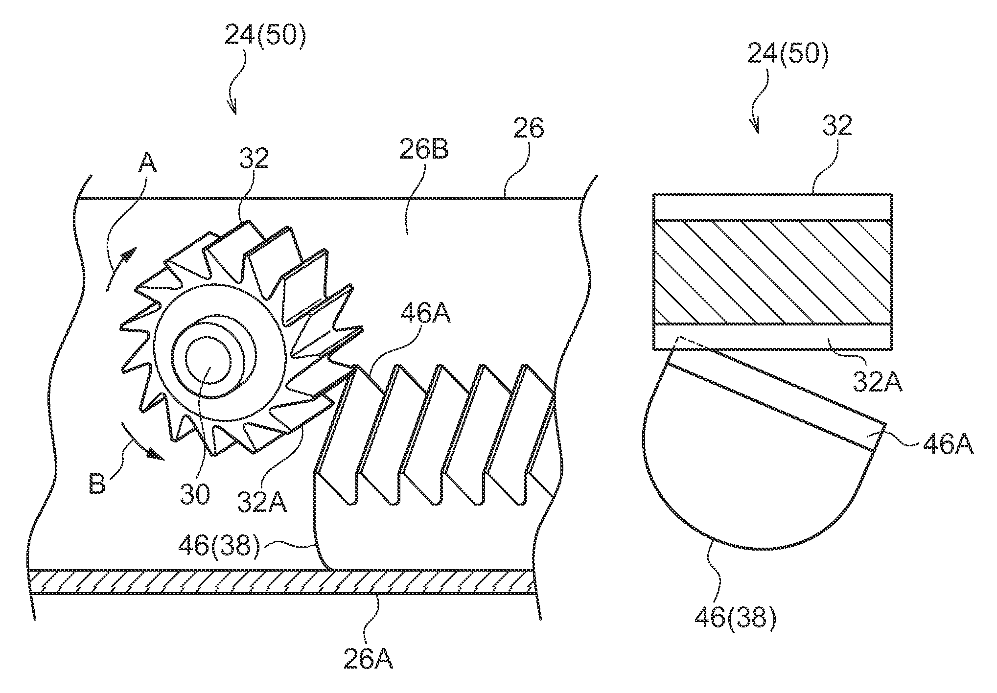
[0069]As illustrated by FIG. 5 and FIG. 8A, in the pre-tensioning mechanism 24 of the webbing take-up device 50 of the present exemplary embodiment, the piston 38 is disposed in a state axially rotated relative to the arrangement thereof in the first exemplary embodiment such that the extension direction of the rack teeth 46A of the piston 38 (the rack 46) is inclined (angled) with respect to the extension direction of the pinion teeth 32A of the pinion 32. Thus, as shown in FIG. 9 and FIG....


PUM


Abstract

In a webbing take-up device, due to actuation of a pre-tensioning mechanism when a vehicle collision, a piston is moved, rack teeth of the piston mesh with pinion teeth of a pinion, causing the pinion rotate and a spool to be rotated in the take-up direction. In a state where a large rotational force in the pull-out direction is acting from an occupant on the pinion, through a webbing and the spool, a rack tooth is broken by a pinion tooth when the rack teeth initially mesh with the pinion teeth, especially by a tip end of the rack tooth meshing with the pinion tooth. Therefore, sticking-in of the pinion teeth rack teeth and the pinion teeth can be suppressed, or easily eliminated, enabling loss in force transmitted from the piston to the pinion to be reduced.

Description

CROSS-REFERENCE TO RELATED APPLICATION[0001]This application claims priority under 35 USC 119 from Japanese Patent Application No. 2013-023780 filed Feb. 8, 2013 the disclosure of which is incorporated by reference herein.BACKGROUND[0002]1. Field of the Invention[0003]The present invention relates to a pre-tensioning mechanism in which a rotating member is rotated and a take-up member is rotated in a take-up direction by a moving member being moved.[0004]2. Related Art[0005]In a seat belt take-up device described in Japanese Patent Application Laid-Open (JP-A) No. 8-207706, a piston rod is moved, and a teeth portion of the piston rod meshes with a teeth portion of a toothed ratchet, thereby rotating the toothed ratchet in the take-up direction and taking up a seat belt by the retractor rotating in the take-up direction.[0006]In the seat belt take-up device therein, it is recognized that the retractor is made capable of rotating integrally with the toothed ratchet even at a time befo...

Claims


Application Information

Patent Timeline
Patent Type & Authority Patents(United States)
IPC IPC(8): B60R22/38B60R22/46
CPCB60R22/46B60R22/4633B60R2022/468
Inventor YANAGAWA, WATARUUKITA, MASARU
Owner KK TOKAI RIKA DENKI SEISAKUSHO
Why Eureka
Try Eureka