Storage rack with multi-direction shuttle
a storage rack and shuttle technology, applied in the direction of transportation and packaging, storage devices, etc., can solve the problems of high power consumption, high cost, complex, etc., and achieve the effect of less stringent requirements
- Summary
- Abstract
- Description
- Claims
- Application Information
AI Technical Summary
Benefits of technology
Problems solved by technology
Method used
Image
Examples
first embodiment
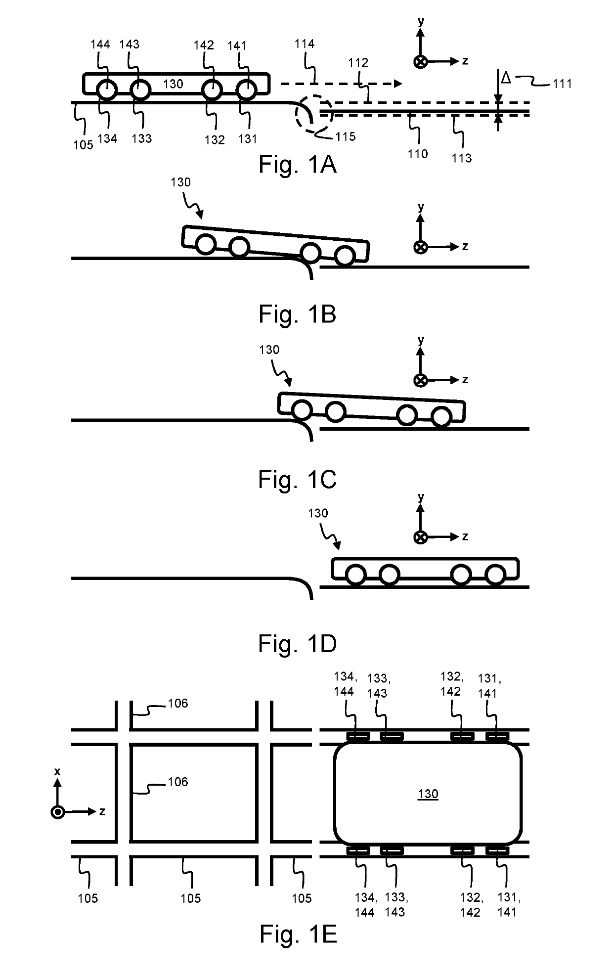
[0065]FIG. 1A to FIG. 1E illustrate such a shuttle 130 and track configuration according to the invention. The shuttle 130 is configured to ride along an aisle track 106, running along the x-direction. At different positions along the aisle track 106, there are track crossings 105. The track crossings are arranged such that rails of the aisle track cross the rails of the track crossing. The track crossing 105 typically runs in a direction substantially orthogonal to the aisle track 106, i.e., along the z-direction.
[0066]By the track crossing, the shuttle 130 may change direction, i.e., change between the x- and z-direction. In order to do so, the shuttle 130 stops at a crossing in the aisle track 106 and then rides onto the rails of the track crossing 105. The track crossing 105 allows the shuttle to access the storage track 110. The storage track 110 is arranged in the same direction as the track crossing 105, i.e., the z-direction.
[0067]The track crossing 105 and storage track 110...
second embodiment
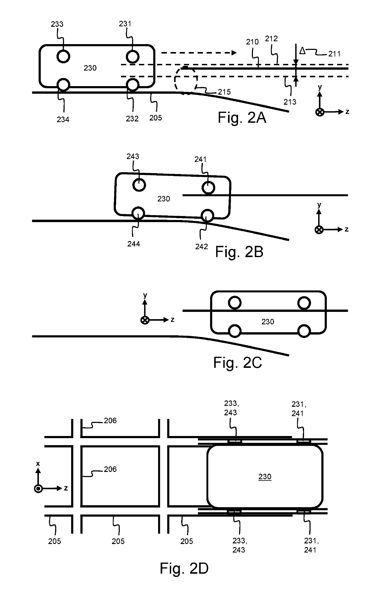
[0074]FIG. 2A to FIG. 2D illustrate a shuttle 230 and track configuration according to the invention. The shuttle 230 is configured to ride along an aisle track 206, indicated as the x-direction. At different positions along the aisle track 206, there are track crossings 205. The track crossings are arranged such that rails of the aisle track cross the rails of the track crossing.
[0075]The track crossing 205 and storage track 210 are spaced apart by a discontinuity 215, i.e., there is an offset 215 in height between rails of the track crossing 205 and the rails of the storage track 210. Because of this offset, the rails of the track crossing 205 and storage track 210 do not need to be aligned precisely with respect to each other as the rail do not need to be connected to each other. This allows a tolerance 211 in height in the placement of the storage track 210 with respect to the track crossing 205. In FIG. 2A, the maximum height of the storage track 210 is indicated by the dashed ...
third embodiment
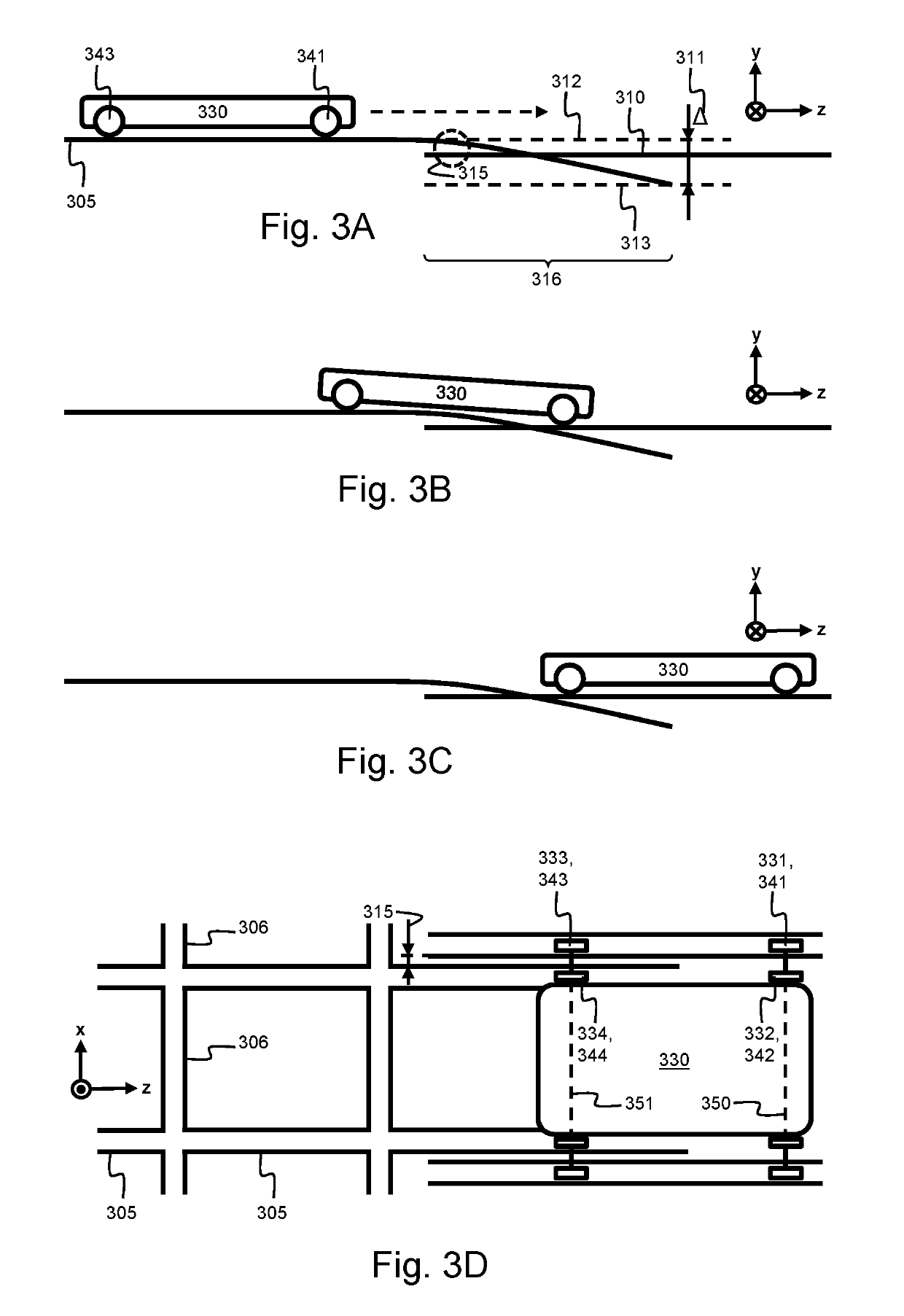
[0082]FIG. 3A to FIG. 3D illustrate a shuttle 330 and track configuration according to the invention. The shuttle 330 is configured to ride along the aisle track 306, indicated as the x-direction. At different positions along the aisle track 306, there are track crossings 305. The track crossings are arranged such that rails of the aisle track 306 cross the rails of the track crossing 305.
[0083]The track crossing 305 and storage track 310 are spaced apart by a discontinuity 315, i.e., there is an offset 315 in width between rails of the track crossing 305 and the rails of the storage track 310. Because of this offset, the rails of the track crossing 305 and storage track 310 do not need to be aligned precisely with respect to each other as the rails do not need to be connected to each other. This allows a tolerance 311 in height in the placement of the storage track 310 with respect to the track crossing 305. In FIG. 3A, the maximum height of the storage track 310 is indicated by th...
PUM
 Abstract
Description
Claims
Application Information
 - R&D
- Intellectual Property
- Life Sciences
- Materials
- Tech Scout
- Unparalleled Data Quality
- Higher Quality Content
- 60% Fewer Hallucinations
Browse by: Latest US Patents, China's latest patents, Technical Efficacy Thesaurus, Application Domain, Technology Topic, Popular Technical Reports.
© 2025 PatSnap. All rights reserved.Legal|Privacy policy|Modern Slavery Act Transparency Statement|Sitemap|About US| Contact US: help@patsnap.com


