Optical scanner with micro-optics for beam combination

a technology of optical scanner and beam combination, applied in the field of optical scanner, can solve the problems of high adjustment cost, difficult production of gratings, high adjustment cost, etc., and achieve the effect of better adjustment of light beams

Inactive Publication Date: 2005-01-13
THOMSON LICENSING SA
View PDF11 Cites 1 Cited by
  • Summary
  • Abstract
  • Description
  • Claims
  • Application Information

AI Technical Summary

Benefits of technology

[0015] For better adjustability of the light beams on the detector, it is advantageous if provision is made of an optical adjustment element, which can be used to influence the spatial position of the first and/or the second light beam. Such an optical adjustment element is for example an essentially plane-parallel plate. As is known, a plane-parallel plate placed obliquely into a light beam generates a beam offset. The latter is dependent on the thickness d of the plate, the angle α of rotation of the plate and the refractive index n. If such a plane-parallel plate, situated only in the beam path of one of the light beams upstream of the detector, is rotated about an axis perpendicular to the light beam, that is to say the angle α is changed, then the position of the light beam on the detector changes. If such a plane-parallel plate is introduced into both beam paths, the positions of both light beams can be changed correspondingly. Moreover, the wavelength dependence of the refractive index of the plane

Problems solved by technology

However, many parts have to be used for such apparatuses, which is associated with high costs and a high adjustment outlay.
High costs are caused especially by the required beam combination cube for combining the different light beams.
However, gratings have a high degree of wavelength dependence, which can lead to problems if the wavelength of the laser d

Method used


Image

  • Optical scanner with micro-optics for beam combination
  • Optical scanner with micro-optics for beam combination
  • Optical scanner with micro-optics for beam combination

Examples


Embodiment Construction

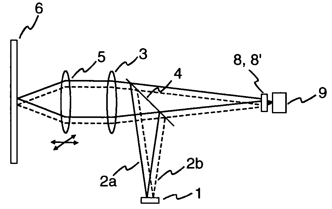
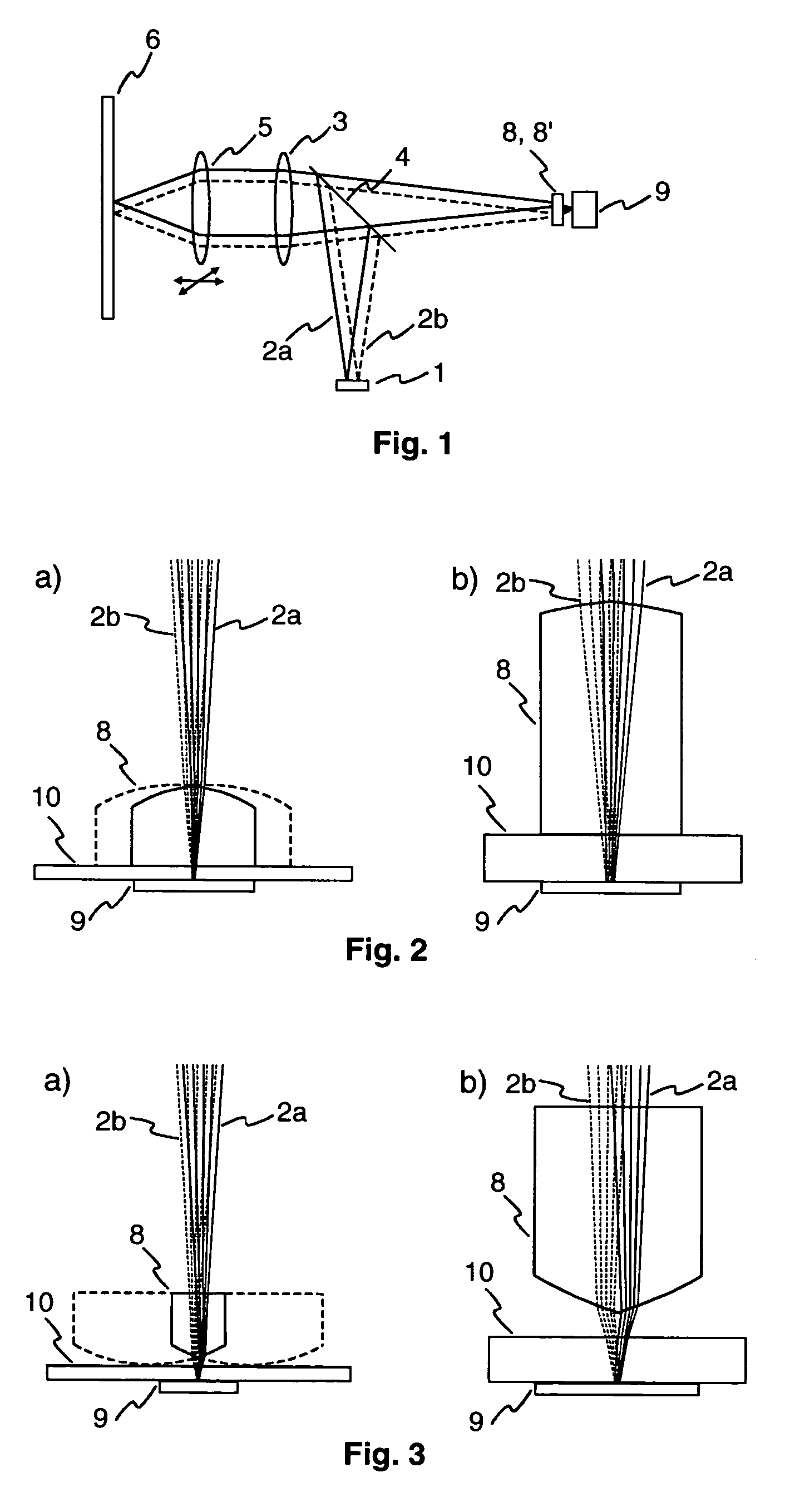
[0026] An optical scanner having a micro-optical element 8 for beam combination is illustrated diagrammatically in FIG. 1. A twin laser diode 1 emits a first light beam 2a and a second light beam 2b. The light beams 2a, 2b are deflected via a half-mirror 4 in the direction of an optical recording medium 6 and collimated with the aid of a collimator lens 3. By means of a movable objective lens 5, the light beams 2a, 2b are focused onto a data track situated on the optical recording medium 6. The objective lens 5 can be moved by an actuator (not shown) in the direction of the optical recording medium 6 and also perpendicularly to the data track in order to keep the focus of the light beams 2a, 2b exactly on the track. The reflected light beams 2a, 2b, which are modulated in accordance with the data stored in the track, are collimated by the objective lens 5 and focused onto a photodetector 9 by the collimator lens 3, passing through the half-mirror 4 in the process. The photodetector ...


PUM


Abstract

An optical scanner having a micro-optical element for combining two light beams is disclosed. The optical scanner has a micro-optical element including two parts, which serves to combine two light beams emitted, by two beam sources on a photodetector. The first part of the micro-optical element influences the first light beam and the second part of the micro-optical element influences the second light beam.

Description

FIELD OF THE INVENTION [0001] The present invention relates to an optical scanner having a micro-optical element for combining two light beams and to an apparatus for reading from and / or writing to optical recording media, which has such an optical scanner. BACKGROUND OF THE INVENTION [0002] Apparatuses for reading from and / or writing to optical recording media which are suitable for different types of optical recording media often require a plurality of beam sources which emit light beams having a different wavelength. One example is apparatuses for reading from and / or writing to DVDs (digital versatile disc), which are usually able to reproduce CDs (compact disc). Whereas a wavelength of 650 nm is used for the DVDs, the CDs are read with a wavelength of 780 nm. The development of optical drives operating with even shorter wavelengths, such as e.g. drives for Blu-Ray Disc, which operate with a wavelength of 405 nm, will also necessitate the use of a plurality of beam sources in the...

Claims


Application Information

Patent Timeline
IPC IPC(8): G02B5/04G02B5/00G11B7/00G11B7/09G11B7/125G11B7/135
CPCG02B5/001G11B7/094G11B7/1275G11B7/1356G11B7/1365Y10S359/904G11B7/1381G11B7/1395G11B2007/0006G11B2007/13727G11B7/1378G02B5/04
Inventor STRAUCH, FRANK
Owner THOMSON LICENSING SA
Why Eureka
Try Eureka