Adjustable length upper frame member for eyeglasses

a technology of eyeglasses and upper frames, which is applied in the direction of instruments, spectales/goggles, multi-purpose tools, etc., can solve the problems of wearers who disregard proper safety procedures, fail to wear protective eyewear, and the lens in this construction does not provide free floating ends, so as to reduce complexity and overall assembly steps, the effect of high adjustmen

Inactive Publication Date: 2005-12-08
SPERIAN EYE & FACE PROTECTION
View PDF45 Cites 44 Cited by
  • Summary
  • Abstract
  • Description
  • Claims
  • Application Information

AI Technical Summary

Benefits of technology

[0009] In this regard, the present invention provides a novel construction for protective eyeglasses that includes numerous points of articulation thereby allowing the eyeglasses to be highly adjustable to suit the needs of virtually all users of the eyeglasses. Further, the present invention utilizes complex, multi-step injection molding techniques to form in-mold-assembly (IMA) components that are then incorporated into the finished eyeglasses thereby reducing complexity and overall assembly steps.

Problems solved by technology

Generally, however, most of these protective eyeglasses are not adapted to be both comfortably worn and adjustable to fit different wearers.
Accordingly, wearers have been forced to wear uncomfortable, poorly fitting protective eyewear, resulting in wearers that disregard proper safety procedures and fail to wear protective eyewear.
However, the lens in this construction does not provide for free floating ends, instead, it is pinned at notches 10 (see FIG. 7).
Further, several separate pieces must be molded and subsequently assembled thereby increasing the complexity of the assembly process.
The difficulty with these prior art protective eyeglasses is that each one is only an incremental improvement and none of them provide a comprehensive solution for manufacturing protective eyeglass that are universally adjustable for individual users while also being comfortable to wear and have a reduced number of individual parts to facilitate assembly.

Method used


Image

  • Adjustable length upper frame member for eyeglasses
  • Adjustable length upper frame member for eyeglasses
  • Adjustable length upper frame member for eyeglasses

Examples


Embodiment Construction

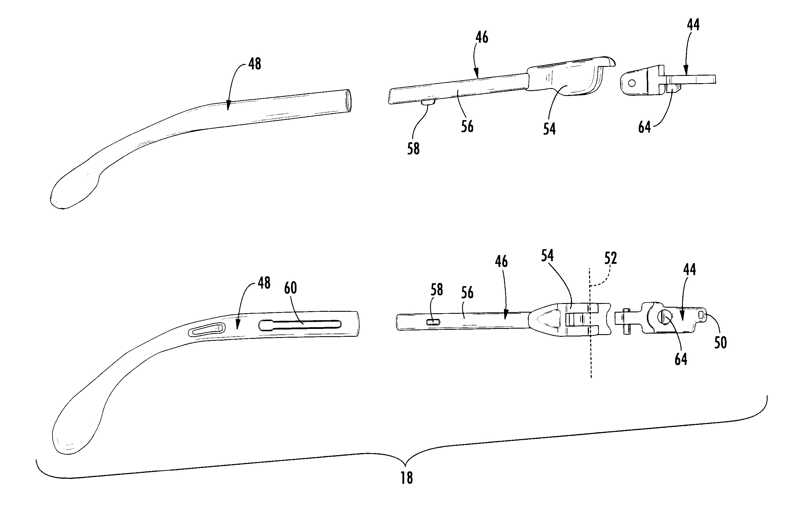
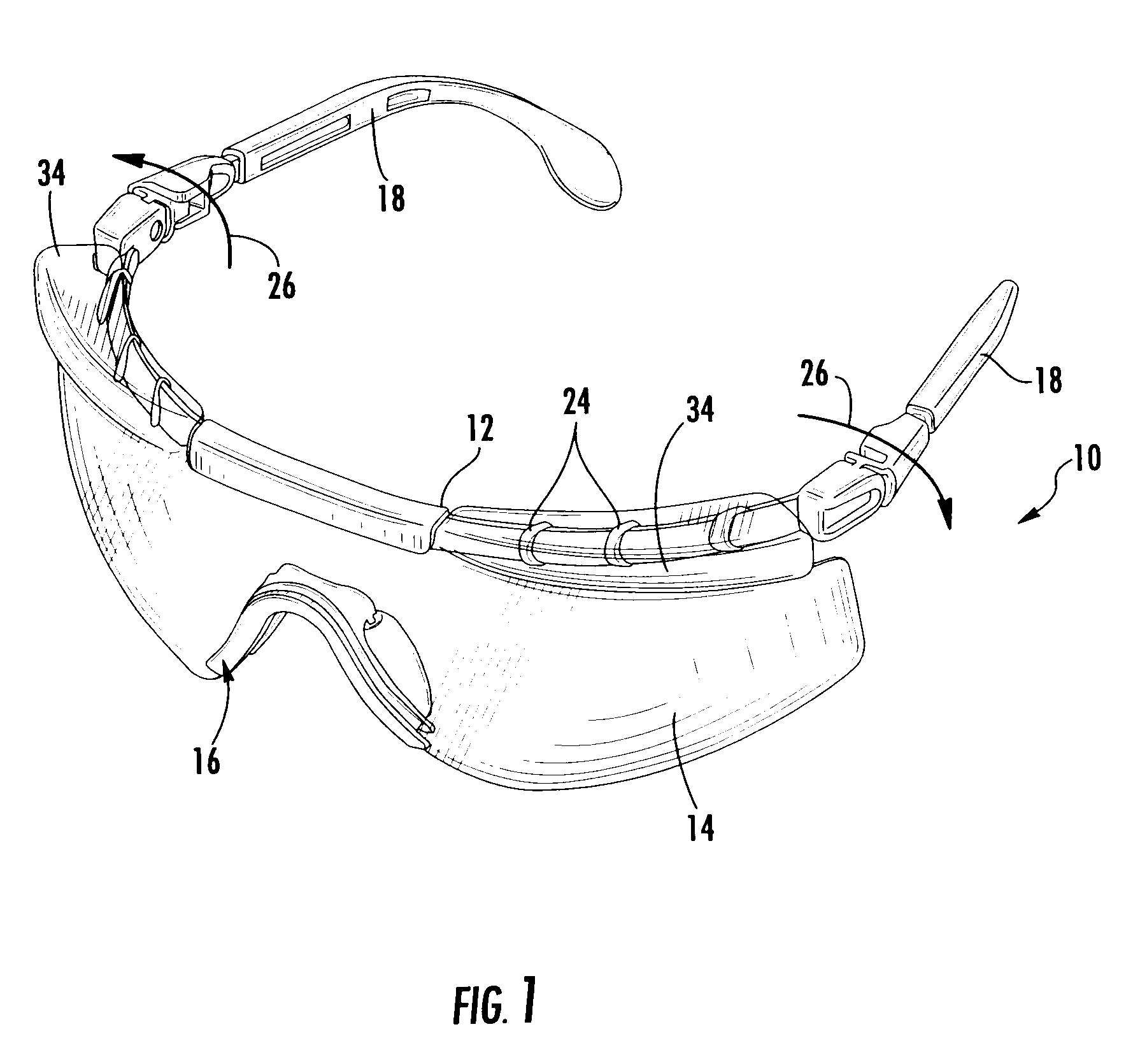
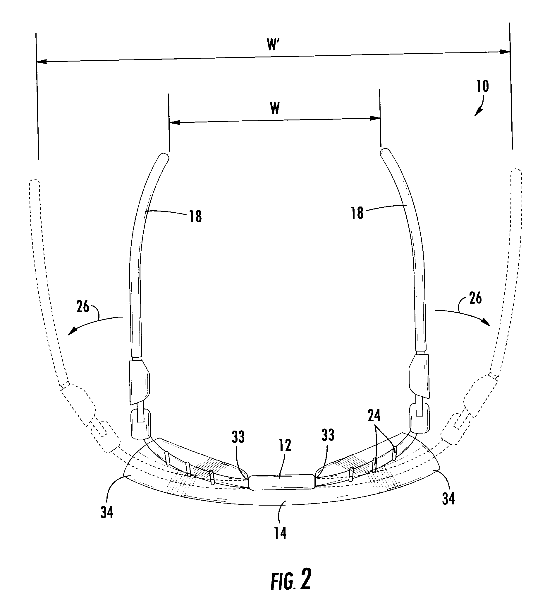
[0033] Now referring to the drawings, a preferred embodiment of the safety eyewear of the instant invention is illustrated and generally indicated at 10 in FIGS. 1-9. As will hereinafter be more fully described, the safety eyewear 10 includes a brow bar 12 that is adapted to receive and support a lens 14, a nose piece 16 that is adapted to be snap received into the nose bridge of the lens 14, and two temple bar assemblies 18 that are snap received into the terminal ends of the brow bar 12.

[0034] The invention utilizes novel multi-shot molding techniques to provide hinge connections and telescoping parts that are formed inside the mold cavity during molding (In-Mold-Assembly or IMA) and thus do not require any additional assembly once the part is removed from the mold cavity. In the preferred embodiment disclosed herein, the molding techniques are particularly important in the formation of adjustable elastomeric nose pads on the nose piece of the eyewear as well as in the integral f...


PUM


Abstract

A frame assembly for eyeglasses is provided wherein the overall width of the eyeglass frame is adjustable by utilizing a telescoping brow bar. The upper frame member or brow bar is formed to include either a pair of telescoping or indexed joints allowing the length of the brow bar to be adjusted thereby placing the hinge points and temple bars further apart from one another. The adjustable length of the brow bar provides excellent adjustability of the overall width of the eyeglass frame in simple mechanical construction. Further, in a unique method of forming the adjustable brow bar assembly a central portion may be formed in a first molding step and an adjustable hinge section is then molded directly over the central portion in a second molding step. The present invention utilizes in-mold-assembly techniques to reduce the assembly steps required to form such an adjustable brow bar assembly while further resulting in an eyeglass frame that has increased adjustability and utility.

Description

CROSS-REFERENCE TO RELATED APPLICATIONS [0001] This application is related to and claims priority from earlier filed provisional patent application No. 60 / 576,367, filed Jun. 2, 2004.BACKGROUND OF THE INVENTION [0002] The present invention relates generally to eyewear assemblies and methods of manufacturing eyewear assemblies. More specifically, the present invention relates to safety eyewear assemblies that are manufactured utilizing multi-shot molding techniques to achieve unique manufacturing and assembly advantages. [0003] In the prior art, there are a large variety of different types of protective eyeglasses that are available for protecting a user's eyes when engaging in hazardous activities. Generally, however, most of these protective eyeglasses are not adapted to be both comfortably worn and adjustable to fit different wearers. Accordingly, wearers have been forced to wear uncomfortable, poorly fitting protective eyewear, resulting in wearers that disregard proper safety pr...

Claims


Application Information

Patent Timeline
Patent Type & Authority Applications(United States)
IPC IPC(8): G02C1/00G02C1/04G02C1/08G02C5/00G02C5/04G02C5/06G02C5/12G02C5/14G02C5/20G02C5/22G02C11/08
CPCG02C5/04G02C5/06G02C5/10G02C5/20Y10T16/526G02C11/08G02C2200/16G02C2200/08G02C5/126G02C5/2263G02C2200/18
Inventor CURCI, RAYMONDFROISSARD, LAURENTMITTERSINKER, GREGORJOBIN, MICHAEL J.
Owner SPERIAN EYE & FACE PROTECTION
Why Eureka
Try Eureka