Optical scanner with micro-optics for beam combination

a technology of optical scanner and beam combination, applied in the field of optical scanner, can solve the problems of high adjustment cost, difficult production of gratings, high adjustment cost, etc., and achieve the effect of better adjustment of light beams

Inactive Publication Date: 2007-09-04
THOMSON LICENSING SA
View PDF14 Cites 0 Cited by
  • Summary
  • Abstract
  • Description
  • Claims
  • Application Information

AI Technical Summary

Benefits of technology

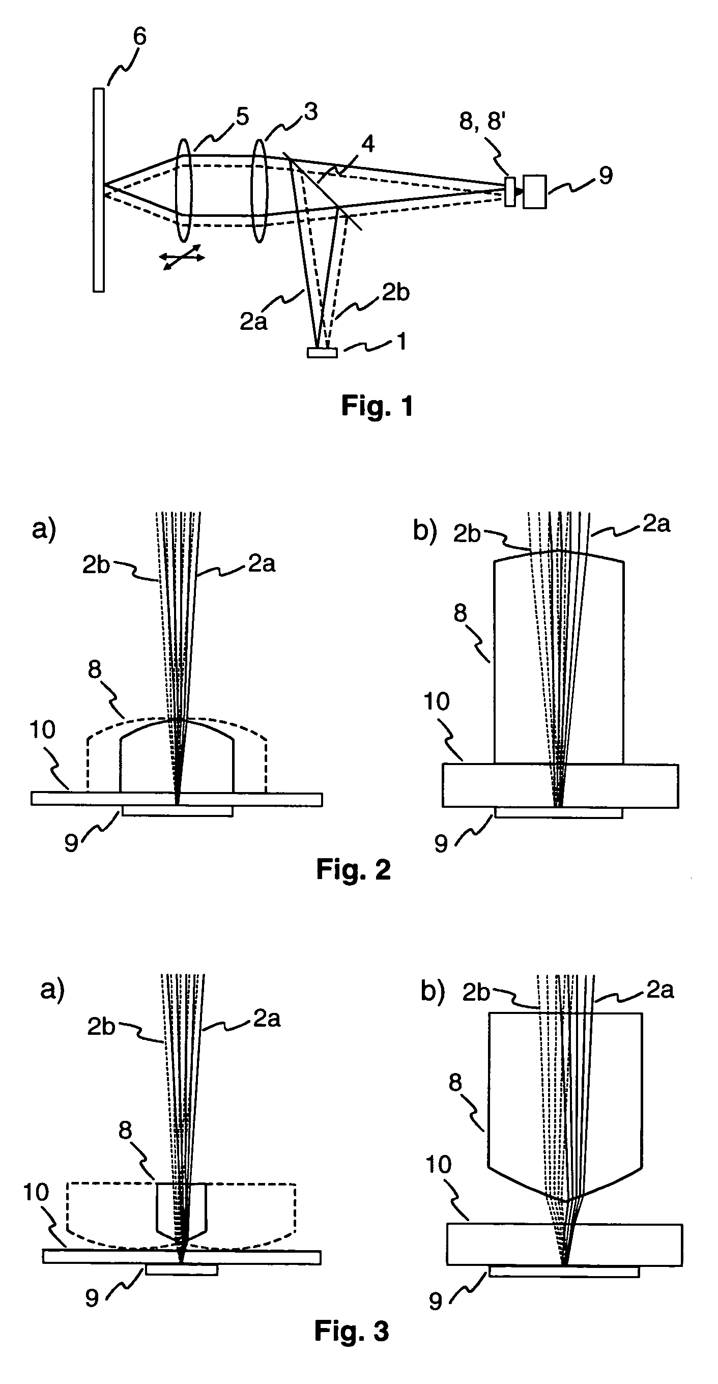
[0008]The micro-optical element is preferably a double prism. The double prism or roof prism results from a micro-optical lens by using the straight line as the simplest form for the curve form of the lens area. The exit area of the micro-optical element is preferably embodied as the double prism since the separation of the light beams is greater there. In this case, the entry area of the micro-optical element may be designed as a lens surface, which can be used to control the size of the light beam on the detector. The lens surface may be configured for example as a spherical or cylindrical area. The latter makes it possible to produce a perfectly round beam cross section on the photodetector area, which leads to a symmetrical S-curve. This is of importance for the servo electronics. In this case, the cylinder has to be rotated such that the plane of curvature corresponds to the plane in which the prism angle is also located.
[0010]The micro-optical element is advantageously arranged at the photodetector. The distance between the two light beams is greatest there, as a result of which the requirements made of the minimization of the micro-optics and the adjustment accuracy are reduced. As an alternative, the micro-optical element is arranged at the beam sources. There, too, the light beams are separated relatively far from one another, thus resulting in less stringent requirements made of the minimization of the micro-optics and the adjustment accuracy in this case as well. Depending on the embodiment, the micro-optical element may cause additional astigmatism in the light beams. An arrangement at the photodetector is preferable in such cases.
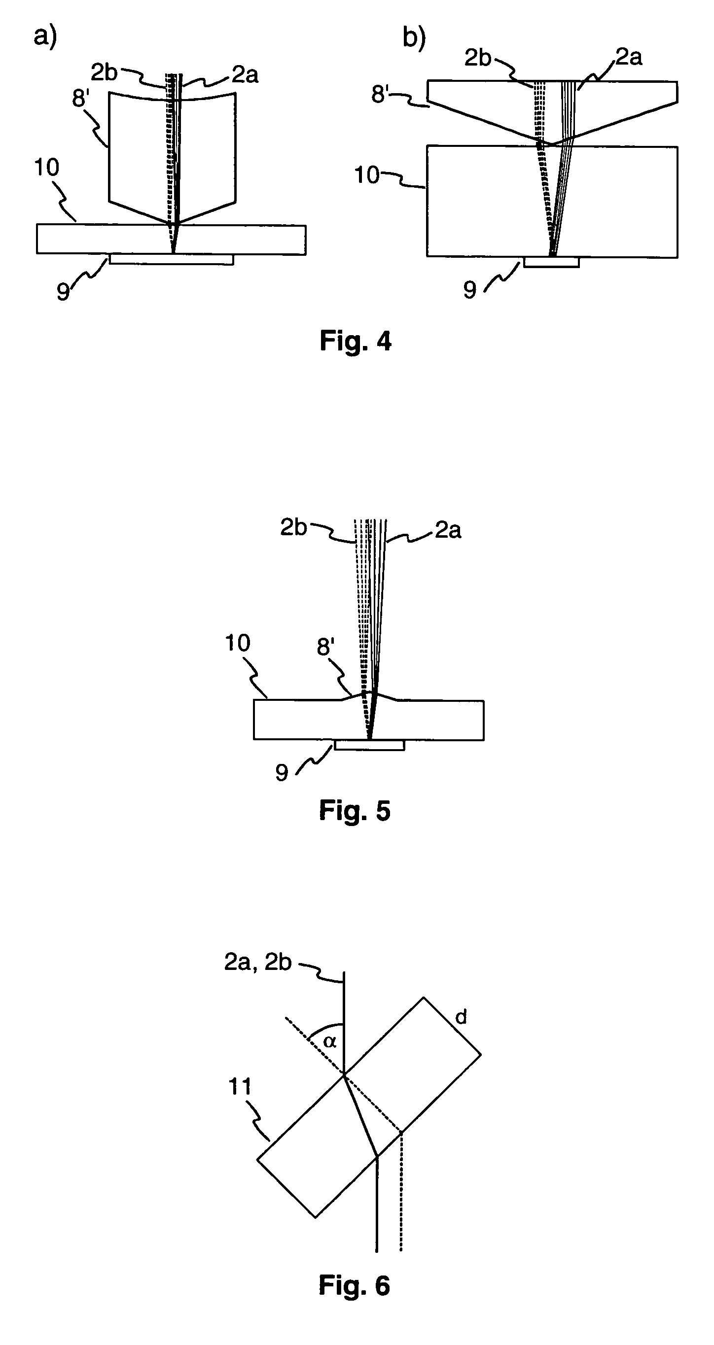
[0015]For better adjustability of the light beams on the detector, it is advantageous if provision is made of an optical adjustment element, which can be used to influence the spatial position of the first and / or the second light beam. Such an optical adjustment element is for example an essentially plane-parallel plate. As is known, a plane-parallel plate placed obliquely into a light beam generates a beam offset. The latter is dependent on the thickness d of the plate, the angle α of rotation of the plate and the refractive index n. If such a plane-parallel plate, situated only in the beam path of one of the light beams upstream of the detector, is rotated about an axis perpendicular to the light beam, that is to say the angle α is changed, then the position of the light beam on the detector changes. If such a plane-parallel plate is introduced into both beam paths, the positions of both light beams can be changed correspondingly. Moreover, the wavelength dependence of the refractive index of the plane-parallel plate can be utilized in order to adapt the distance between the two light beams. For this purpose, a common plate is used for both light beams. Since the refractive index is a function of the wavelength, a rotation of the plate leads to an offset between the two light beams, which has a varying magnitude. The distance between the laser spots on the detector thus becomes adjustable. In the course of adjustment, it is necessary in this case to track the detector. The optical adjustment element is particularly advantageous for a so-called single detector, in which one detector is used for both light beams. However, it may equally be used in the case of a so-called twin detector, in which two detectors are combined to form a unit, for adjusting the light beams.
[0016]As an alternative, the micro-optical element itself may also serve as the adjustment element. An effect analogous to the plane-parallel plate is achieved by rotating the roof prism, for example, about an axis parallel to the roof edge.

Problems solved by technology

However, many parts have to be used for such apparatuses, which is associated with high costs and a high adjustment outlay.
High costs are caused especially by the required beam combination cube for combining the different light beams.
However, gratings have a high degree of wavelength dependence, which can lead to problems if the wavelength of the laser diodes drifts with increasing temperature.
Moreover, the gratings are not easy to produce since there are blazed gratings.
According to present-day prior art, this concept cannot be applied to all types of optical storage media since correspondingly rapid twin photodetectors still do not exist for example for the high speeds occurring in the case of DVD-ROM.

Method used


Image

  • Optical scanner with micro-optics for beam combination
  • Optical scanner with micro-optics for beam combination
  • Optical scanner with micro-optics for beam combination

Examples


Embodiment Construction

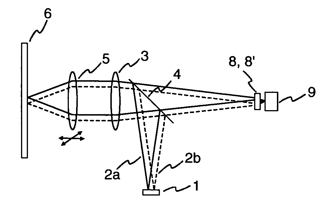
[0026]An optical scanner having a micro-optical element 8 for beam combination is illustrated diagrammatically in FIG. 1. A twin laser diode 1 emits a first light beam 2a and a second light beam 2b. The light beams 2a, 2b are deflected via a half-mirror 4 in the direction of an optical recording medium 6 and collimated with the aid of a collimator lens 3. By means of a movable objective lens 5, the light beams 2a, 2b are focused onto a data track situated on the optical recording medium 6. The objective lens 5 can be moved by an actuator (not shown) in the direction of the optical recording medium 6 and also perpendicularly to the data track in order to keep the focus of the light beams 2a, 2b exactly on the track. The reflected light beams 2a, 2b, which are modulated in accordance with the data stored in the track, are collimated by the objective lens 5 and focused onto a photodetector 9 by the collimator lens 3, passing through the half-mirror 4 in the process. The photodetector 9...


PUM

PropertyMeasurementUnit
wavelengthaaaaaaaaaa

Abstract

An optical scanner having a micro-optical element for combining two light beams is disclosed. The optical scanner has a micro-optical element including two parts, which serves to combine two light beams emitted, by two beam sources on a photodetector. The first part of the micro-optical element influences the first light beam and the second part of the micro-optical element influences the second light beam.

Description

FIELD OF THE INVENTION[0001]The present invention relates to an optical scanner having a micro-optical element for combining two light beams and to an apparatus for reading from and / or writing to optical recording media, which has such an optical scanner.BACKGROUND OF THE INVENTION[0002]Apparatuses for reading from and / or writing to optical recording media which are suitable for different types of optical recording media often require a plurality of beam sources which emit light beams having a different wavelength. One example is apparatuses for reading from and / or writing to DVDs (digital versatile disc), which are usually able to reproduce CDs (compact disc). Whereas a wavelength of 650 nm is used for the DVDs, the CDs are read with a wavelength of 780 nm. The development of optical drives operating with even shorter wavelengths, such as e.g. drives for Blu-Ray Disc, which operate with a wavelength of 405 nm, will also necessitate the use of a plurality of beam sources in the futu...

Claims


Application Information

Patent Timeline
Patent Type & Authority Patents(United States)
IPC IPC(8): G02B26/08G02B5/04G02B5/00G11B7/00G11B7/09G11B7/125G11B7/135
CPCG02B5/001G11B7/1275G11B7/1356G11B7/1365G11B7/1378G11B7/1381G11B7/1395G11B7/094G11B2007/0006G11B2007/13727Y10S359/904G02B5/04
Inventor STRAUCH, FRANK
Owner THOMSON LICENSING SA
Why Eureka
Try Eureka