Image editor, and method and computer-readable medium therefor
a technology of image editor and computer, applied in the field of image editor, can solve the problems of heavy burden on the user who operates the mobile terminal, complicated positional relationship among objects, etc., and achieve the effect of preventing a heavy burden from being imposed on the user
- Summary
- Abstract
- Description
- Claims
- Application Information
AI Technical Summary
Benefits of technology
Problems solved by technology
Method used
Image
Examples
first specific example
[0091](First Specific Example)
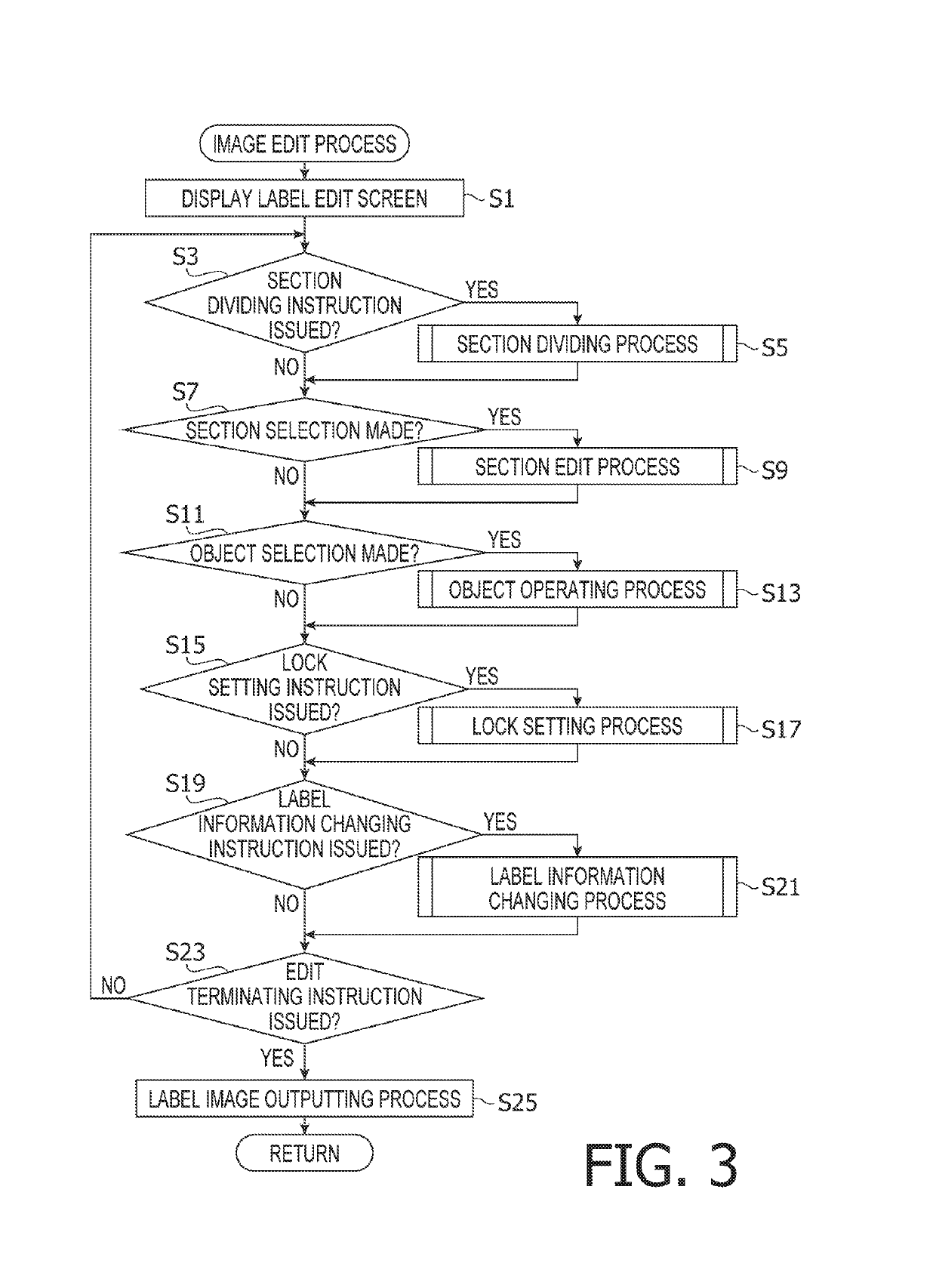
[0092]In the example shown in FIG. 10A, the user operates the icon 200 to select the text object 112B (S11: Yes, and S13). Further, by a drag-and-drop operation, the user moves the text object 112B to the left within the section 120C (S71: Yes, and S73: Yes). At this time, a center coordinate of the text object 112B is placed on a left side of a center coordinate of the symbol object 111B and on a right side of a left end of the section 120C (S75, and S77: Yes).
[0093]Thereby, as shown in FIG. 10B, in the section 120C, the text object 112B is moved to a left side of the symbol object 111B (S79). Namely, in the section 120C, an arrangement order of the existing objects 110 is changed. Thus, the user is allowed to freely change the layout of a plurality of objects 110 within an arbitrary section 120.
second specific example
[0094](Second Specific Example)
[0095]In the example shown in FIG. 10A, the user operates the icon 200 to select the section 120C (S7: Yes, and S9). Further, the user operates the icon 200 to place a frame object 113 in the section 120C (S61: Yes). Thereby, the frame object 112 is added into the section 120C (S63). In the section 120C, the layout of the symbol object 111B, the text object 112B, the symbol object 111C, and the frame object 113 is automatically adjusted (S65).
[0096]Thereby, as shown in FIG. 10C, the frame object 113 is placed along an inner edge of the section 120C. The symbol object 111B, the text object 112B, and the symbol object 111C are closely placed with display sizes thereof being reduced, within the frame object 113. Thus, the user is allowed to place one or more arbitrary objects 110 in each section 120. In each section 120, the layout of all objects 110 placed therein including a newly-placed object 110 is automatically adjusted in accordance with the displa...
third specific example
[0097](Third Specific Example)
[0098]In the example shown in FIG. 10A, the user operates the icon 200 to select the text object 112A (S11: Yes, and S13). As shown in FIG. 11A, by a drag-and-drop operation, the user moves the text object 112A from the section 120B to an outside area of the label image 100 (S71: Yes, S73: Yes, S75, and S77: No). Further, the user operates the icon 200 to select and execute a section dividing instruction (S3: Yes, and S5).
[0099]Subsequently, as shown in FIG. 11B, the user operates the icon 200 to place a new dividing line 130C in the section 120B that is a blank field (S31, and S33: Yes). Thereby, the dividing line 130C is added onto the label image 100 (S35: No, and S37). The dividing line 130C is a straight line vertically extending across the section 120B. The section 120B is divided by the dividing line 130C into two sections 120D and 120E adjoining in the left-to-right direction. In response to this, the section information is updated (S39).
[0100]F...
PUM
 Abstract
Description
Claims
Application Information
 - R&D
- Intellectual Property
- Life Sciences
- Materials
- Tech Scout
- Unparalleled Data Quality
- Higher Quality Content
- 60% Fewer Hallucinations
Browse by: Latest US Patents, China's latest patents, Technical Efficacy Thesaurus, Application Domain, Technology Topic, Popular Technical Reports.
© 2025 PatSnap. All rights reserved.Legal|Privacy policy|Modern Slavery Act Transparency Statement|Sitemap|About US| Contact US: help@patsnap.com


