Image processing apparatus and image processing method
a technology of image processing apparatus and image processing method, which is applied in the field of image tone conversion processing, can solve the problem that the technique is not necessarily optimized for the image device to be used, and achieve the effect of suitable image tone conversion
- Summary
- Abstract
- Description
- Claims
- Application Information
AI Technical Summary
Benefits of technology
Problems solved by technology
Method used
Image

Examples
first embodiment
[0026]A first embodiment of an image processing apparatus according to the present invention is described below using an example of an image processing apparatus that performs a tone conversion (tone compression) of an M-level input image into an N-level (where M>N) output image.
[0027]
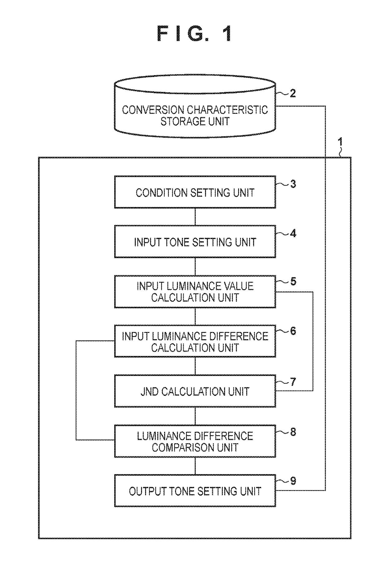
[0028]FIG. 1 is a block diagram illustrating a configuration of an image processing apparatus according to a first embodiment. As described above, an image processing apparatus 1 is an apparatus that calculates a tone-conversion characteristic for converting an input image represented by M levels into an output image of N levels. Also, a conversion characteristic storage unit 2 is an apparatus for storing the tone-conversion characteristic that the image processing apparatus 1 calculated, specifically an input tone value and an output tone value corresponding to the input tone value.
[0029]A condition setting unit 3 sets a condition in a tone-conversion characteristic calculation. An input tone setting ...
second embodiment
[0062]In the second embodiment, another embodiment for deciding a conversion characteristic is described. Specifically, in the second embodiment, a tone reproduction characteristic of an image output device (an imaging element or the like) is used in place of using a JND which is a characteristic of visual perception in the first embodiment as a luminance difference threshold.
[0063]
[0064]FIG. 6 is a block diagram illustrating a configuration of an image processing apparatus according to the second embodiment. Note that the condition setting unit 3 to the input luminance difference calculation unit 6 and the luminance difference comparison unit 8 to the output tone setting unit 9 are similar to the functional units of the same names in FIG. 1, and therefore explanation thereof is omitted.
[0065]An image processing apparatus 601, similarly to in the first embodiment, is an apparatus that calculates a tone-conversion characteristic for converting an input image represented by M levels i...
third embodiment
[0076]In the third embodiment, an embodiment is explained in which tone conversion processing is performed by, based on the image capturing condition (exposure condition) for when the input image is captured, calculating a correspondence relation of an absolute luminance in relation to each tone of the input data, and then calculating a tone-conversion characteristic based on the luminance difference for one tone of an input tone and a JND.
[0077]
[0078]FIG. 9 is a block diagram illustrating a configuration of an image processing apparatus according to the third embodiment. An image processing apparatus 901 is an apparatus that converts image data represented by M levels into image data of N levels. An image acquisition apparatus 902 is an apparatus that obtains image data of a digital camera or the like.
[0079]An image input unit 903 reads from the image acquisition apparatus 902 image data as input data. A tone number setting unit 904 sets the tone numbers of the input data and the o...
PUM
 Abstract
Description
Claims
Application Information
 - R&D
- Intellectual Property
- Life Sciences
- Materials
- Tech Scout
- Unparalleled Data Quality
- Higher Quality Content
- 60% Fewer Hallucinations
Browse by: Latest US Patents, China's latest patents, Technical Efficacy Thesaurus, Application Domain, Technology Topic, Popular Technical Reports.
© 2025 PatSnap. All rights reserved.Legal|Privacy policy|Modern Slavery Act Transparency Statement|Sitemap|About US| Contact US: help@patsnap.com