Image display device
a display device and image technology, applied in the field of image display devices, can solve the problems of observers' difficulty in visually recognizing images and insufficient brightness of images, and achieve the effect of brightening images and improving image forming characteristics (the visibility) of images
- Summary
- Abstract
- Description
- Claims
- Application Information
AI Technical Summary
Benefits of technology
Problems solved by technology
Method used
Image
Examples
first embodiment
(First Embodiment)
[Image Display Device]
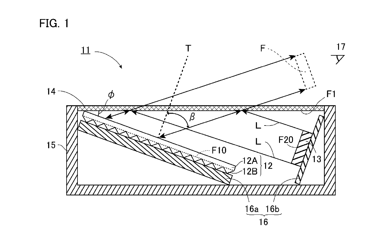
[0041]An embodiment that is an example of an image display device according to the present invention will be described with reference to FIG. 1.
[0042]An image display device 11 according to the embodiment has a retroreflective member 12, an image output device 13, and a half mirror 14. In the example of the embodiment, the image display device 11 has a box-shaped frame 15 and a base 16, in addition to the retroreflective member 12, the image output device 13, and the half mirror 14.
[0043]The frame 15 has a box shape with a bottom wall and sidewalls in which one face is opened. The half mirror 14 covers the opening, and the sidewalls of the frame 15 support the half mirror 14. The retroreflective member 12, the image output device 13, and the base 16 are disposed on the one face F1 side of the half mirror 14, i.e. these components are disposed in the space defined by the frame 15 and the half mirror 14.
[0044]The base 16 has a first base 16a on ...
second embodiment
(Second Embodiment)
[0152]Next, a second embodiment of the present invention will be described in detail with reference to FIG. 4. Note that, components the same as or equivalent to the components of the first embodiment are designated the same reference signs to omit the duplicate description unless otherwise specified.
[0153]FIG. 4 is a schematic cross-sectional view of an image display device according to the second embodiment of the present invention. As shown in FIG. 4, an image display device 21 according to the embodiment is mainly different from the image display device 11 of the first embodiment in that the image output device 13 is disposed opposite to the retroreflective member 12, with the half mirror 14 provided between the image output device 13 and the retroreflective member 12.
[0154]In the embodiment, the image output device 13 is disposed along the wall face of the frame 15, and the half mirror 14 is slanted to the image output face F20 of the image output device 13. ...
third embodiment
(Third Embodiment)
[0156]Next, a third embodiment of the present invention will be described in detail with reference to FIG. 5. Note that, components the same as or equivalent to the components of the second embodiment are designated the same reference signs to omit the duplicate description unless otherwise specified.
[0157]FIG. 5 is a schematic cross-sectional view of an image display device according to the third embodiment of the present invention. As shown in FIG. 5, an image display device 31 according to the embodiment is mainly different from the image display device 21 according to the second embodiment in that a second retroreflective member 112 is further disposed on the same side where the image output device 13 is located relative to the half mirror 14. Therefore, the retroreflective member 112 is disposed opposite to the retroreflective member 12, with the half mirror 14 provided between the retroreflective member 112 and the retroreflective member 12.
[0158]The retroref...
PUM
 Abstract
Description
Claims
Application Information
 - R&D
- Intellectual Property
- Life Sciences
- Materials
- Tech Scout
- Unparalleled Data Quality
- Higher Quality Content
- 60% Fewer Hallucinations
Browse by: Latest US Patents, China's latest patents, Technical Efficacy Thesaurus, Application Domain, Technology Topic, Popular Technical Reports.
© 2025 PatSnap. All rights reserved.Legal|Privacy policy|Modern Slavery Act Transparency Statement|Sitemap|About US| Contact US: help@patsnap.com


