Image display device

a display device and image technology, applied in the field of image display devices, can solve the problems of observers' difficulty in visually recognizing images and insufficient brightness of images, and achieve the effect of brightening images and improving image forming characteristics (the visibility) of images

Active Publication Date: 2018-06-07
NIPPON CARBIDE KOGYO KK
View PDF4 Cites 3 Cited by
  • Summary
  • Abstract
  • Description
  • Claims
  • Application Information

AI Technical Summary

Benefits of technology

[0024]The present inventors found that the brightness of images displayed by the image display device is improved using a retroreflective member formed with prismatic retroreflective elements having a height of 10 μm or more and 1,000 μm or less and the tilt angle of the optical axis at zero degree. An object of the present invention is to brighten images to be displayed by an image display device and to improve the image forming characteristics (the visibility) of images.
[0032]The image display device according to the present invention includes a retroreflective member formed with prismatic retroreflective elements whose height is 10 μm or more and 1,000 μm or less and whose tilt angle of the optical axis is zero degree. Accordingly, the image display device can brighten images to be displayed, and can improve the image forming characteristics (the visibility) of images.

Problems solved by technology

The image display devices equipped with the previously existing retroreflective members have problems in that the brightness of images is insufficient and observers have the difficulty of visually recognizing images.

Method used


Image

  • Image display device
  • Image display device
  • Image display device

Examples


first embodiment

[Image Display Device]

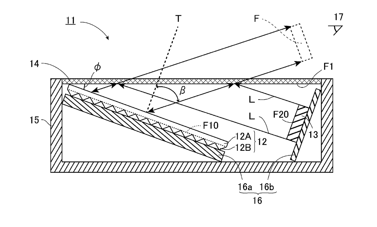
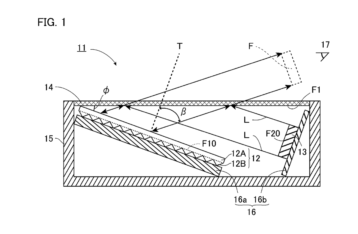
[0040]An embodiment that is an example of an image display device according to the present invention will be described with reference to FIG. 1.

[0041]An image display device 11 according to the embodiment has a retroreflective member 12, an image output device 13, and a half mirror 14. In the example of the embodiment, the image display device 11 has a box-shaped frame 15 and a base 16, in addition to the retroreflective member 12, the image output device 13, and the half mirror 14.

[0042]The frame 15 has a box shape with a bottom wall and sidewalls in which one face is opened. The half mirror 14 covers the opening, and the sidewalls of the frame 15 support the half mirror 14. The retroreflective member 12, the image output device 13, and the base 16 are disposed on the one face F1 side of the half mirror 14, i.e. these components are disposed in the space defined by the frame 15 and the half mirror 14.

[0043]The base 16 has a first base 16a on which the retroref...

second embodiment

[0151]Next, a second embodiment of the present invention will be described in detail with reference to FIG. 4. Note that, components the same as or equivalent to the components of the first embodiment are designated the same reference signs to omit the duplicate description unless otherwise specified.

[0152]FIG. 4 is a schematic cross-sectional view of an image display device according to the second embodiment of the present invention. As shown in FIG. 4, an image display device 21 according to the embodiment is mainly different from the image display device 11 of the first embodiment in that the image output device 13 is disposed opposite to the retroreflective member 12, with the half mirror 14 provided between the image output device 13 and the retroreflective member 12.

[0153]In the embodiment, the image output device 13 is disposed along the wall face of the frame 15, and the half mirror 14 is slanted to the image output face F20 of the image output device 13. The arrangement fac...

third embodiment

[0155]Next, a third embodiment of the present invention will be described in detail with reference to FIG. 5. Note that, components the same as or equivalent to the components of the second embodiment are designated the same reference signs to omit the duplicate description unless otherwise specified.

[0156]FIG. 5 is a schematic cross-sectional view of an image display device according to the third embodiment of the present invention. As shown in FIG. 5, an image display device 31 according to the embodiment is mainly different from the image display device 21 according to the second embodiment in that a second retroreflective member 112 is further disposed on the same side where the image output device 13 is located relative to the half mirror 14. Therefore, the retroreflective member 112 is disposed opposite to the retroreflective member 12, with the half mirror 14 provided between the retroreflective member 112 and the retroreflective member 12.

[0157]The retroreflective member 112...


PUM


Abstract

An image display device includes a half mirror, an image output device configured to output a light beam to one face of the half mirror, and a retroreflective member configured to retroreflect at least one of a light beam mirror-reflected off the one face of the half mirror and a light beam transmitted through the one face of the half mirror. The retroreflective member has a base material layer and a plurality of prismatic retroreflective elements formed on one face or two faces of the base material layer. The height of the prismatic retroreflective elements is 10 μm or more and 1,000 μm or less. The tilt angle of the optical axis of the prismatic retroreflective elements is zero degree.

Description

TECHNICAL FIELD[0001]The present invention relates to an image display device equipped with a retroreflective member.BACKGROUND ART[0002]As image display devices that can visually recognize three-dimensional images with no use of dedicated eyeglasses and that include a retroreflective member, an image output device, and a half mirror are widely known.[0003]Patent Literature 1, for example, discloses a three-dimensional image projection system including a projector, a half mirror, and a retroreflective screen. In the projection system, an image projected from the projector is applied to the half mirror and reflected off the surface of the mirror. The image is then applied to the retroreflective screen, and retroreflected at the screen to the half mirror. The image again applied to the half mirror is transmitted through the half mirror, and then a high-quality three-dimensional image is displayed.[0004]Patent Literature 2 discloses an image-forming optical system including a half mirr...

Claims


Application Information

Patent Timeline
Patent Type & Authority Applications(United States)
IPC IPC(8): G02B27/09G03B21/20G02B30/60
CPCG02B27/0977G03B21/2006G02B5/124G02B30/60G02B30/56
Inventor HOUZYOU, TAKUMAHAYASHI, CHIHIRO
Owner NIPPON CARBIDE KOGYO KK
Why Eureka
Try Eureka