Formed lid, method for fitting the lid to container, and sealing method

a technology of lids and containers, applied in the field of formed lids, can solve the problems of not being fully satisfactory in terms of productivity, taking time for heat fusion, and not being able to achieve the effect of fully satisfying the needs of consumers, accurate supply of containers, and reliably fitting containers

Active Publication Date: 2019-06-11
TOYO SEIKAN KAISHA LTD
View PDF21 Cites 3 Cited by
  • Summary
  • Abstract
  • Description
  • Claims
  • Application Information

AI Technical Summary

Benefits of technology

[0021]The formed lid of the present invention is a lid preferably for use in a lid fitting device which automatically supplies a formed lid from above to a container being transported, and presses the formed lid from above to fit it to the container. The introducing section formed with the two tapers different in the taper angle is formed below the fitting section of the formed lid. Even when the formed lid is supplied from above to the container moving for transport in the filling and sealing steps, therefore, the formed lid can be accurately supplied to the container and reliably fitted to the container. That is, the second tapered section with a large taper angle in the formed lid supplied from above is easily engageable with the inner peripheral end (opening end) of the flange section of the container rearward with respect to the travel direction of the container. Thus, the formed lid can be prevented from falling off the container. Moreover, the first tapered section with a small taper angle facilitates the introduction of the formed lid into the container along the opening end of the container. Thus, the formed lid can be easily centered with respect to the container.
[0022]Furthermore, the stepped section is formed in the inner side wall section of the formed lid, and the taper is further formed in the lower inner side wall section. Even if a plurality of the formed lids are stacked, therefore, the formed lid located above can be effectively inhibited from tightly engaging the formed lid located below. Consequently, the formed lid can be supplied from the stacked state of the formed lids, and excels in stackability.
[0023]With the method for fitting the formed lid to a container according to the present invention, the second tapered section of the formed lid is brought into contact with the part of the container rearward in the travel direction of the container. As a result, the formed lid can be allowed to follow the transportational movement of the container. Consequently, the formed lid does not slip down from the container, and the formed lid can be reliably supplied to the container. Moreover, the formed lid can be centered in alignment with the opening of the container by the action of the first tapered section of the formed lid. Hence, even when the container lid is transported at a high speed, the formed lid can be reliably fitted to the container.
[0024]Besides, sealing is performed by laser welding, whereby sealing of the container can be carried out continuously. This effect, coupled with the use of the above-described formed lid, can lead to a further increase in high speed productivity.

Problems solved by technology

Welding by heat sealing, however, takes time for heat fusion and subsequent cooling, and is not fully satisfactory in terms of productivity.
In a thick-walled container or the like, heat conduction takes time, and productivity decreases.
Thus, there are limitations on the wall thickness, and the problem arises that the degrees of freedom of the container and lid shapes are low.
In the case of filling contents having a self-generated pressure or hot filling, in particular, a gas in a head space thermally expanded by sealing heat escapes from the sealing region in a molten state, thereby posing the possibility of seal peeling.

Method used


Image

  • Formed lid, method for fitting the lid to container, and sealing method
  • Formed lid, method for fitting the lid to container, and sealing method
  • Formed lid, method for fitting the lid to container, and sealing method

Examples


Embodiment Construction

(Formed Lid)

[0030]A formed lid according to the present invention will be described using the accompanying drawings.

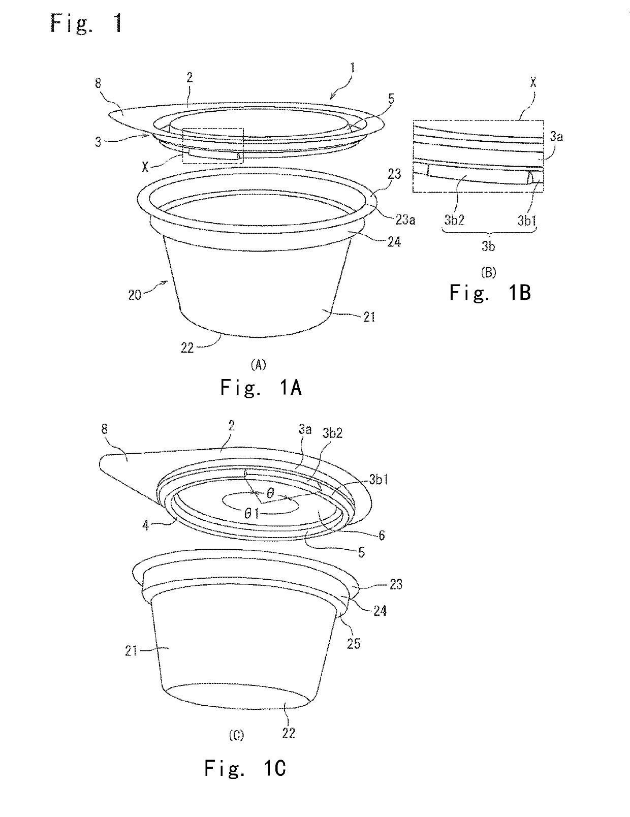
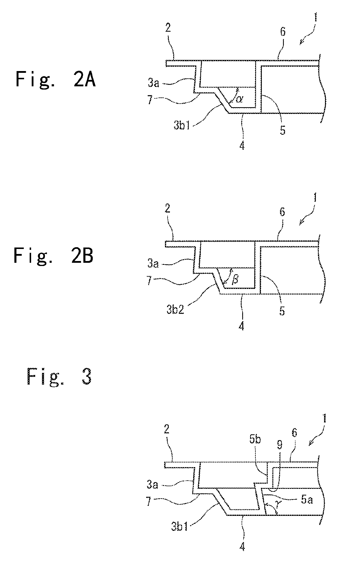
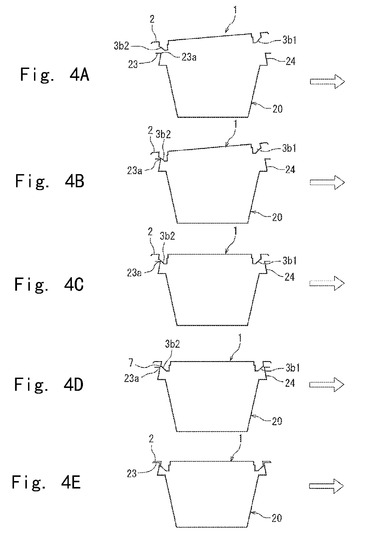
[0031]By reference to FIGS. 1A to 1C and FIGS. 2A, 2B, a formed lid 1 of the present invention is roughly composed of a flange section 2, an outer side wall section 3 suspending from the inner peripheral edge of the flange section 2, an annular section 4 extending horizontally and inwardly from the lower end of the outer side wall section 3, an inner side wall section 5 extending upwardly from the inner peripheral edge of the annular section 4, and a top panel 6 located horizontally and inwardly starting from the upper end of the inner side wall section 5. Partly in the flange section 2, a grip section 8 wider than other parts of the flange section 2 is formed. By holding the grip section 8 and pulling it upward, the formed lid 1 can be opened.

[0032]In the above-mentioned basic configuration of the formed lid according to the present invention, it is important for the ...


PUM


Abstract

A drop lid-shaped formed lid to be fittably applied to a container having a flange section is formed with a flange, a fitting section extending downwardly from the flange, and an introducing section below the fitting section. The introducing section is composed of first and second tapered sections whose inner diameters each decrease downwardly. The taper angle β of the second tapered section is larger than the taper angle α of the first tapered section, and the second tapered section is formed in an arcuate shape smaller than a range in which the first tapered section is formed.

Description

CROSS REFERENCE TO RELATED APPLICATIONS[0001]This application is a National Stage of International Application No. PCT / JP2014 / 083202 filed Dec. 16, 2014, claiming priority based on Japanese Patent Application No. 2013-260770, filed Dec. 18, 2013, the contents of all of which are incorporated herein by reference in their entirety.TECHNICAL FIELD[0002]This invention relates to a formed lid which can be fitted to a container having a flange section, and a method for fitting them. More specifically, the invention relates to a formed lid which can be reliably supplied and fitted to the container even under high speed conditions, has good productivity and is capable of sealing.BACKGROUND ART[0003]As a formed lid which can be fitted to a cup-shaped container having a flange section, a drop lid-shaped one is known which generally comprises a side wall suspending downwardly from the inner edge of a flange section, and a top panel formed at the lower end of the side wall.[0004]For such a comb...

Claims


Application Information

Patent Timeline
Patent Type & Authority Patents(United States)
IPC IPC(8): B65B7/28B65B51/22B65D77/20B65D43/08B65D43/06B65D43/02
CPCB65D43/065B65B7/2878B65B51/22B65D43/022B65D43/08B65D77/20B65D77/2024B65B7/28B65D2543/00842B65D2543/00027B65D2543/00092B65D2543/00296B65D2543/00425B65D2543/00509B65D2543/00648B65D2543/00657B65D2543/00685B65D2543/00759B65D2543/00768B65D2543/00796
Inventor SHINOZAKI, KIYOTAKASAWADA, MAKOTOSHINAGAWA, YOSHIAKI
Owner TOYO SEIKAN KAISHA LTD
Why Eureka
Try Eureka