Binding component holding sheet, binding component separation mechanism and bookbinding apparatus

a technology of binding components and separation mechanisms, which is applied in the field of binding component separation mechanisms and bookbinding apparatuses, can solve the problems of difficult to take out the coil, inability to securely apply a force to separate the inability to secure the separation of the coil from the sheet, so as to reduce the number of punch chad generation

Inactive Publication Date: 2019-08-13
MAX CO LTD
View PDF18 Cites 1 Cited by
  • Summary
  • Abstract
  • Description
  • Claims
  • Application Information

AI Technical Summary

Benefits of technology

[0039]According to the present invention, the binding component is directly held with being offset to the binding component holding sheet. Therefore, it is possible to securely apply a force for detaching the binding component from the binding component holding sheet to the binding component holding sheet at a side at which a protrusion amount of the binding component is greater.
[0040]Also, according to the present invention, when the binding component is attached to the binding component holding sheet, the binding component of multiple turns is exposed to the other side of the binding component holding sheet. Thereby, it is possible to check that the binding component is attached to the binding component holding sheet, from one side and the other side of the binding component holding sheet.
[0041]Also, the escape hole is configured to have the length corresponding to multiples turns of the binding component in the axial direction, so that the punch chad generated upon a manufacturing process of the escape hole is large and thus it is possible to reduce the number of generation of the punch chad in the manufacturing process.
[0042]According to the present invention, during the relative movement of the binding component holding sheet and the contact part, the binding component is contacted against the contact part, so that it is possible to separate the binding component from the binding component holding sheet. Accordingly, it is possible to separate the binding component from the binding component holding sheet with the simple configuration.

Problems solved by technology

When a plurality of coils are stored in a box or the like, the coils get entangled each other, so that it is difficult to take out the coil.
However, in a configuration where the coils are held at substantial center positions of the coils in a radial direction of the coil by the sheet, it is not possible to securely apply a force for separating the coil from the sheet, to the coil.

Method used


Image

  • Binding component holding sheet, binding component separation mechanism and bookbinding apparatus
  • Binding component holding sheet, binding component separation mechanism and bookbinding apparatus
  • Binding component holding sheet, binding component separation mechanism and bookbinding apparatus

Examples


first embodiment

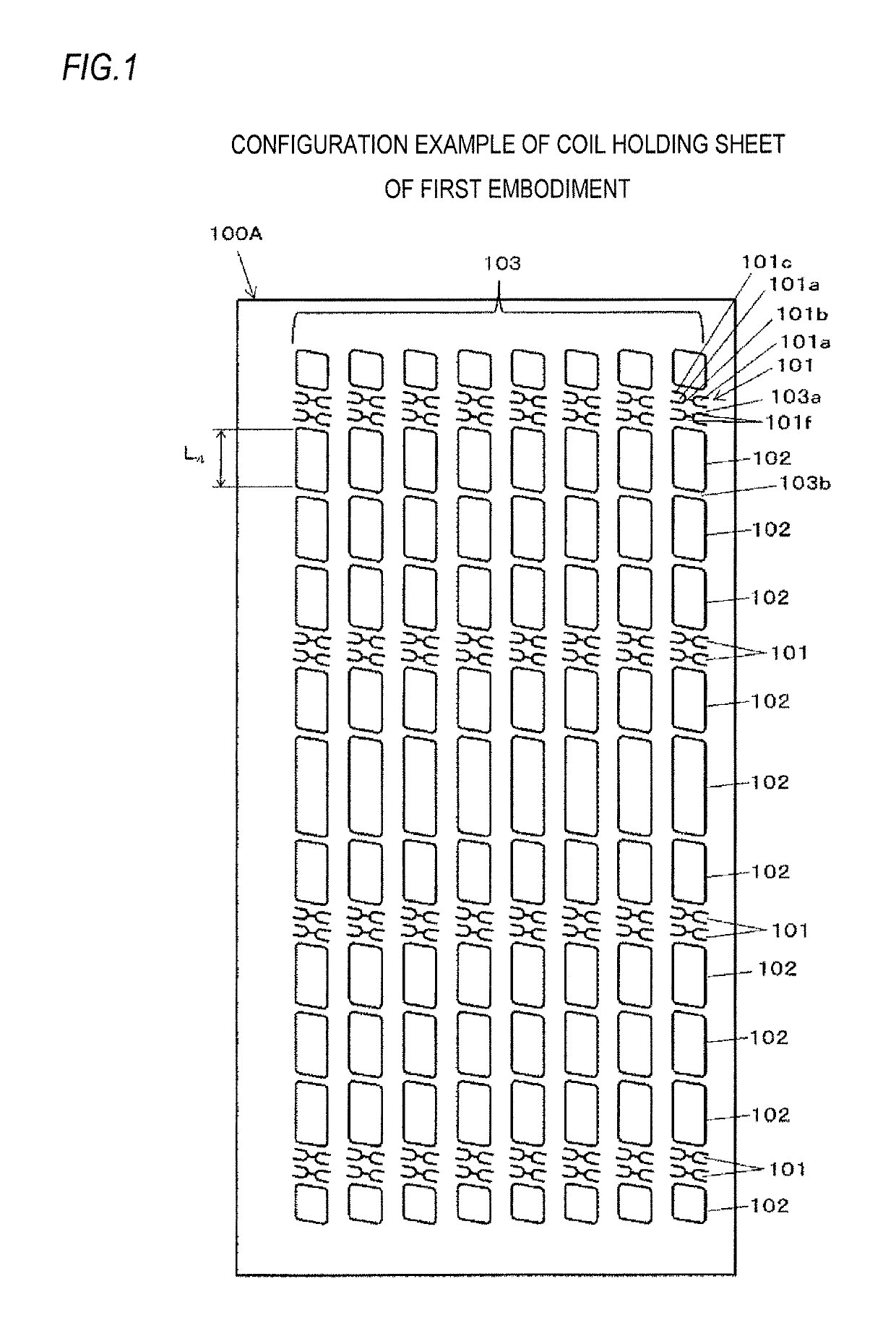
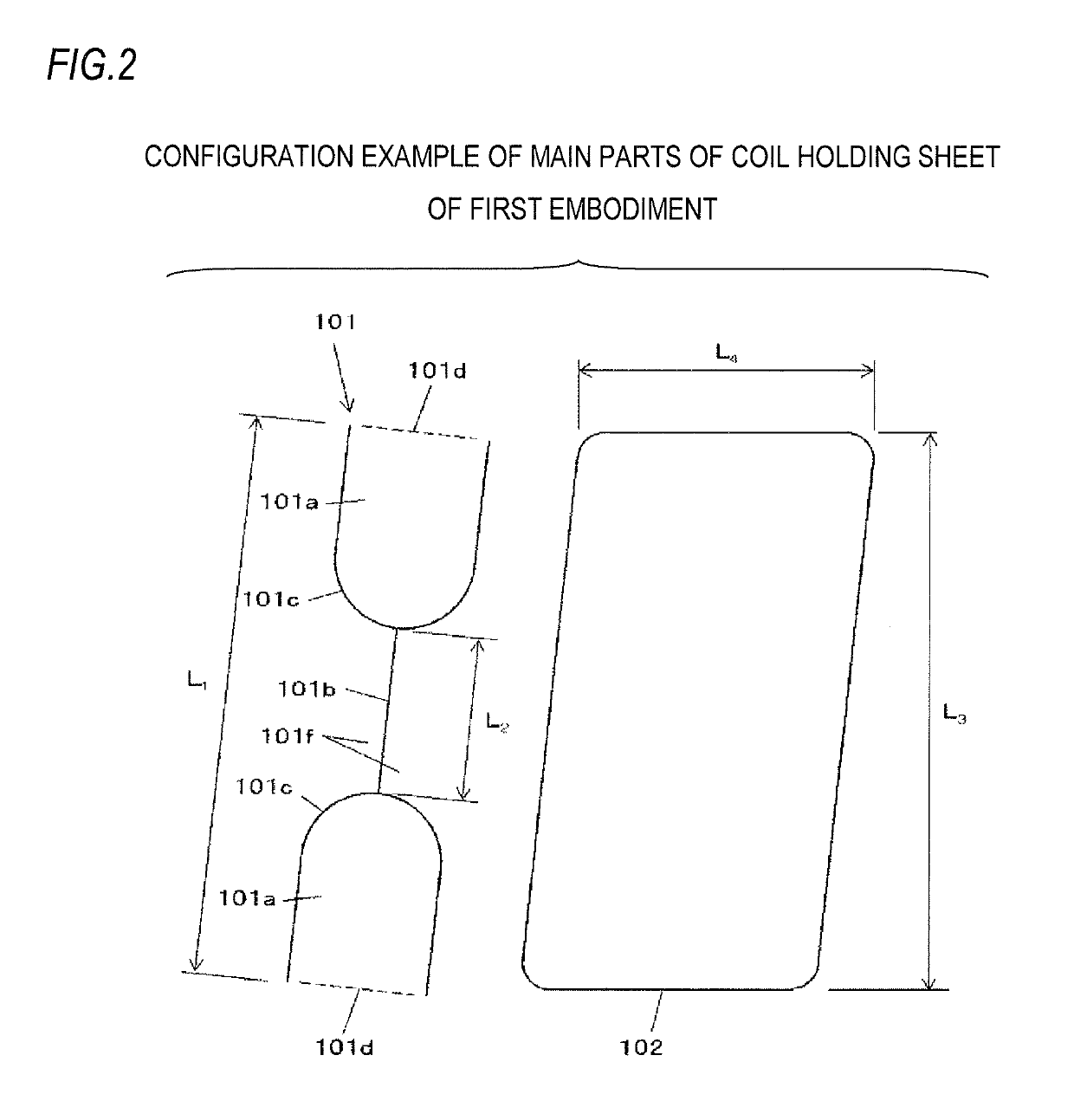
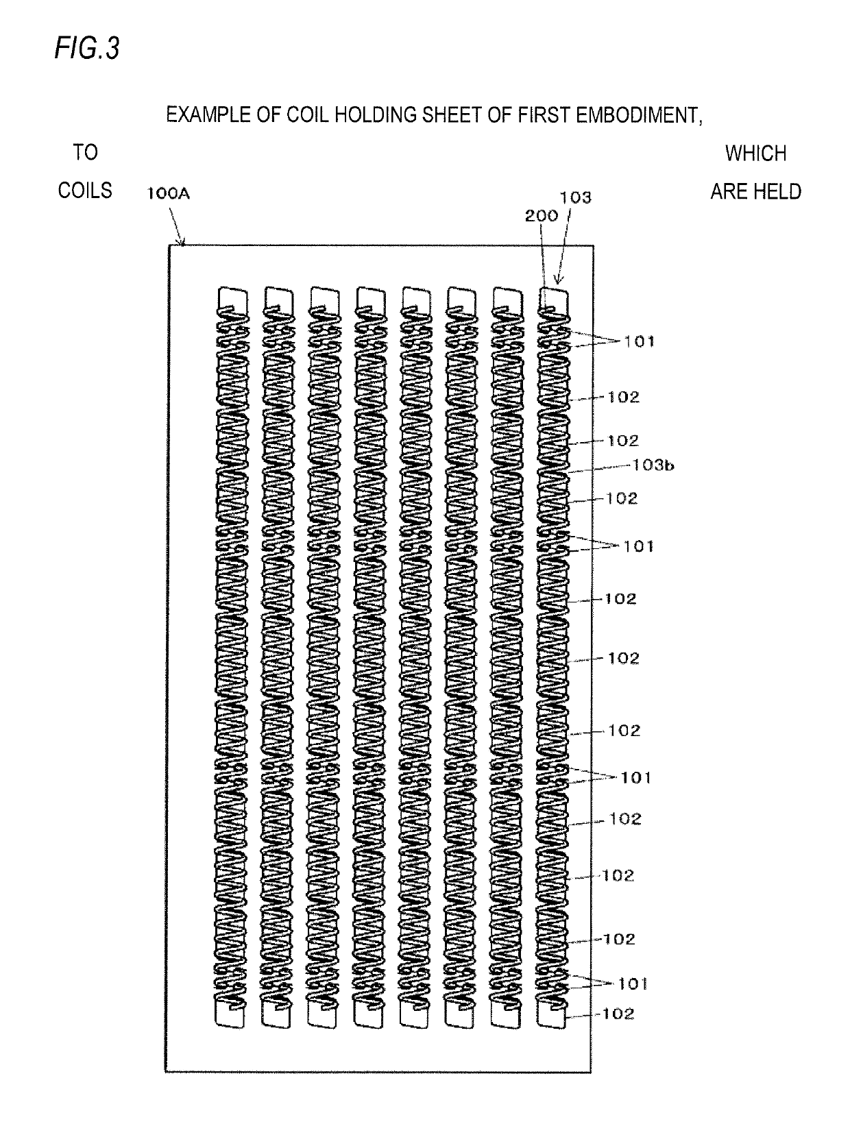
[0192]Also, FIGS. 8 and 9 are side views depicting a configuration of main parts of the coil holding sheet of the first embodiment, to which coils are held, and FIG. 10 is a front view depicting examples of the coil that is to be held by the coil holding sheet.

[0193]First, a coil 200 that is to be held by a coil holding sheet 100A is described with reference to FIG. 10 and the like. The coil 200 is an example of the binder and the binding component and is configured by spirally winding a wire rod such as resin, metal or the like with predetermined pitches. The coil 200 is flexible and can be deformed. For example, the coil 200 can be bent from an axially extending shape and can be returned from the bent shape to the axially extending shape.

[0194]An axial length L of the coil 200 is tailored to a size of a sheet, which is a binding target (which will be described later). Also, a pitch P of the coil 200 is tailored to an interval of holes that are to be formed in the sheet by a bookbi...

second embodiment

[0302]The coil holding sheet 100B has the holder forming places 103a, at which the holders 104 are formed, at a plurality of places of the coil holding row 103 along the axial direction of the coil 200. In the second embodiment, the holder forming places 103a are formed at four places spaced with predetermined intervals along the axial direction of the coil 200.

[0303]Also, the coil holding sheet 100B has at least one holder 104 provided at each of the holder forming places 103a. In the second embodiment, two sets of the holders 104 are provided at each of the holder forming places 103a in conformity to the pitch P of the coil 200.

[0304]The escape hole 102 is configured by an opening penetrating the front and back of the coil holding sheet 100B and having a shape by which a circumferential portion of the coil 200 can be inserted and pulled out. The escape holes 102 are provided in parallel with the holder forming places 103a along the axial direction of the coil 200 held to the coil ...

third embodiment

[0382]The coil holding sheet 100C has the holder forming places 103a, at which the holders 105 are formed, at a plurality of places of the coil holding row 103 along the axial direction of the coil 200. In the third embodiment, the holder forming places 103a are formed at four places spaced with predetermined intervals along the axial direction of the coil 200.

[0383]Also, the coil holding sheet 100c has at least one holder 105 provided at each of the holder forming places 103a. In the third embodiment, two sets of the holders 105 are provided at each of the holder forming places 103a in conformity to the pitch P of the coil 200.

[0384]The escape hole 102 is configured by an opening penetrating the front and back of the coil holding sheet 100C and having a shape by which a circumferential portion of the coil 200 can be inserted and pulled out. The escape holes 102 are provided in parallel with the holder forming places 103a along the axial direction of the coil 200 held to the coil ho...


PUM


Abstract

A binding component holding sheet is configured to detachably hold a binding component obtained by spirally winding a wire rod and includes a holder configured to hold the binding component by insertion of a circumferential portion of the spirally wound binding component. The holder is configured to hold the binding component so that an area greater than a half of the binding component in a circumferential direction protrudes to one side of the binding component holding sheet and an area less than the half of the binding component in the circumferential direction protrudes to the other side of the binding component holding sheet.

Description

TECHNICAL FIELD[0001]The present invention relates to a binding component holding sheet configured to detachably hold a binding component for binding sheets, a binding component separation mechanism configured to separate a binding component from a binding component holding sheet configured to detachably hold a binding component for binding sheets, and a bookbinding apparatus configured to make a booklet by binding a plurality of sheets formed with holes with a binding component.BACKGROUND ART[0002]As a binder configured to bind a plurality of sheets, a binding component, which is referred to as a coil obtained by spirally winding a wire rod of resin, metal or the like, has been suggested. In a bookbinding operation of using the coil, the coil is manually inserted into the holes formed in sheets from side surfaces of the sheets.[0003]In contrast, a bookbinding apparatus, which includes a sheet platen and a coil insertion mechanism configured to axially convey the coil while rotating...

Claims


Application Information

Patent Timeline
Patent Type & Authority Patents(United States)
IPC IPC(8): B42B5/12B42B5/10B42F13/04B42F13/16
CPCB42B5/123B42B5/103B42F13/04B42F13/165B42B5/12B42P2241/24
Inventor HAKOZAKI, KATSUYAIGATA, KAZUYAKISHI, KAZUHIKO
Owner MAX CO LTD
Why Eureka
Try Eureka