Method and apparatus for occlusion removal

a technology of occlusion and occlusion plate, which is applied in the field of method and apparatus for occlusion plate removal, can solve the problems of tissue ischemia (i.e. lack of oxygen and nutrients), death and health care expenditure, and inability to carry out surgery, etc., and achieves the effects of reducing neurological damage, reducing pain, and reducing pain

a technology of occlusion and occlusion plate, which is applied in the field of method and apparatus for occlusion plate removal, can solve the problems of tissue ischemia (i.e. lack of oxygen and nutrients), death and health care expenditure, and inability to carry out surgery, etc., and achieves the effects of reducing neurological damage, reducing pain, and reducing pain

US10383751B2Active Publication Date: 2019-08-20PERFLOW MEDICAL

Image

  • Method and apparatus for occlusion removal
  • Method and apparatus for occlusion removal
  • Method and apparatus for occlusion removal

Examples


Embodiment Construction

[0078]I. Overview:

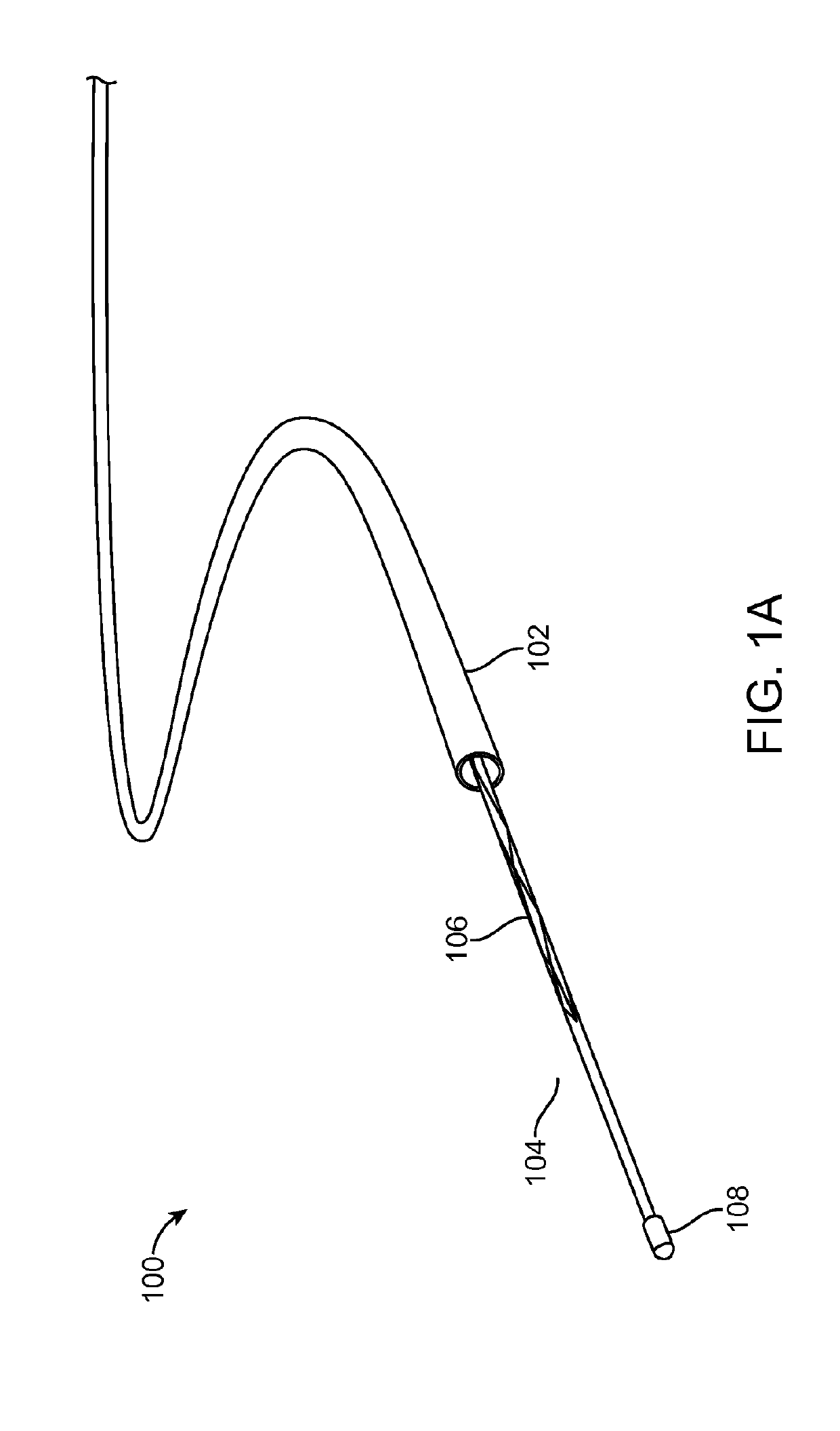
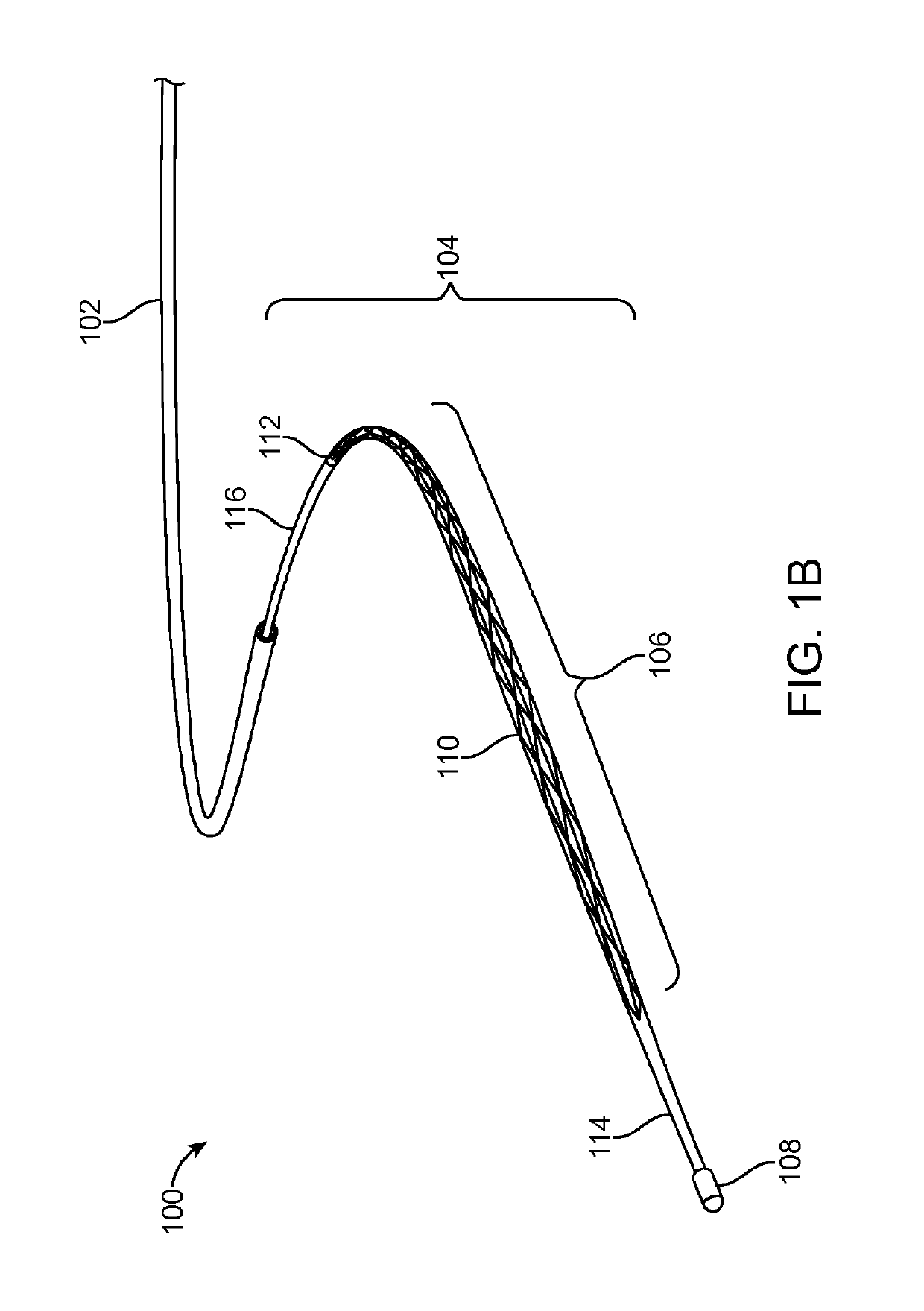
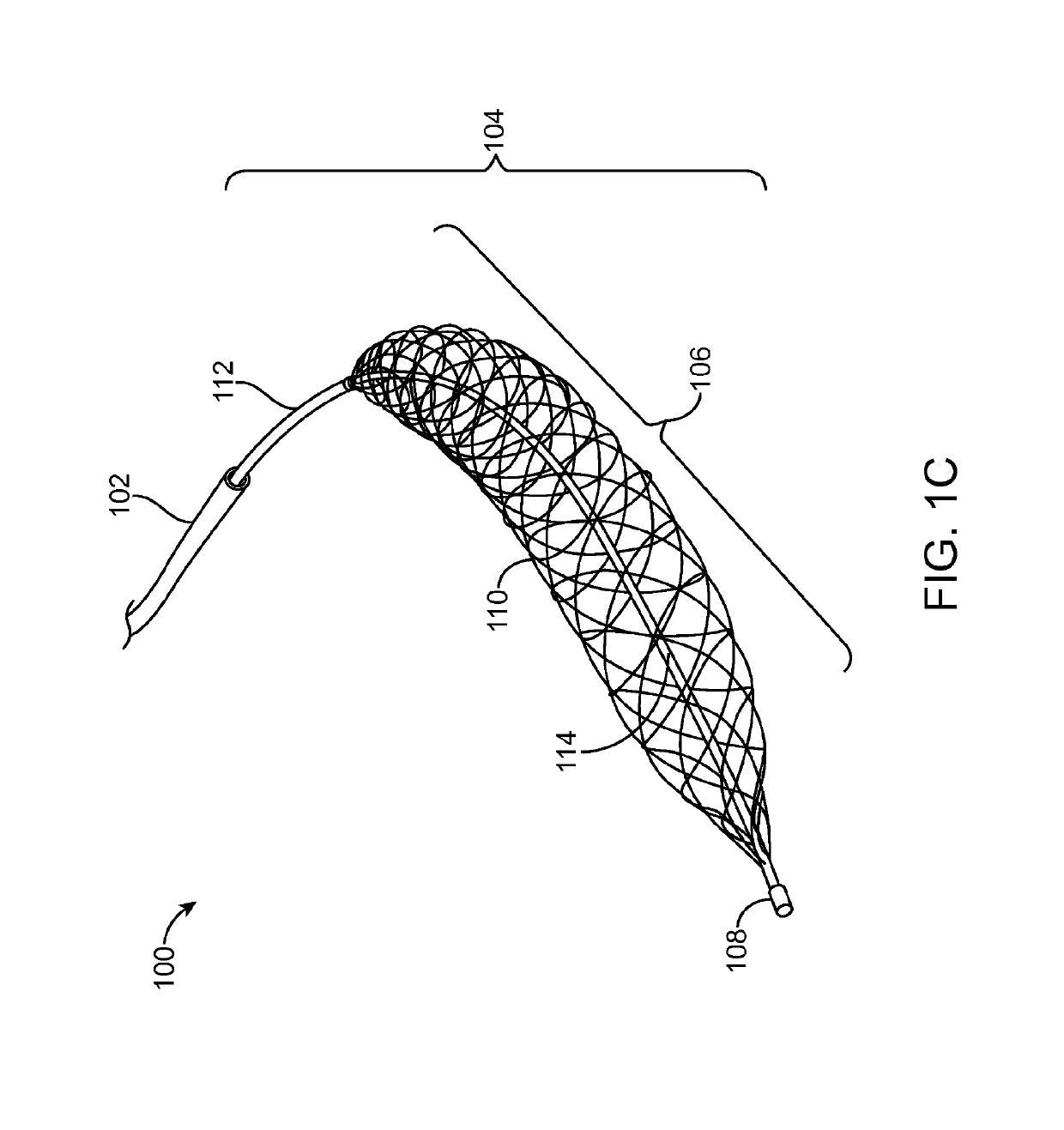
[0079]Embodiments of the invention related to a micro-catheter device having an expandable member. In one embodiment, the expandable member has spirally wrapped (e.g., multiple crossing helixes) and woven filaments in a basket-like configuration. The filaments can be constructed from super-elastic Ni—Ti, with the exception of two filaments constructed from Pt—Ir for radiopacity. In one embodiment sixteen filaments are used, while in another, eight filaments are used.

[0080]The proximal ends of the filaments may be connected to a tubular shaft having a small lumen, while the distal ends of the filaments are interconnected to a common joint. A central pull-wire can be connected to the common joint. The pull-wire can be slideable within the small lumen and may be moved relative to the rest of the microcatheter to cause expansion and contraction of the expandable member.

[0081]The expandable member can have a relaxed configuration with a diameter in a range from about 1 ...


PUM


Abstract

A system for removing a thrombus. The system includes an expandable device that maintains axially fixed engagement with the thrombus. The expandable device applies a first force to the thrombus according to surrounding vessel size. The expandable device applies a second force to the thrombus according to an increased vessel size to maintain axially fixed engagement.

Description

CROSS REFERENCE TO RELATED APPLICATION DATA[0001]The present application is a National Phase of PCT Patent Application No. PCT / US2013 / 021942 having International filing date of Jan. 17, 2013 which is related to and claims the benefit of priority under 35 USC § 119(e) of U.S. Provisional Application Nos. 61 / 679,508 filed Aug. 3, 2012, 61 / 693,026 filed Aug. 24, 2012, and 61 / 587,617 filed Jan. 17, 2012. The contents of the above applications are all incorporated by reference as if fully set forth herein in their entirety for all purposes.BACKGROUND OF THE INVENTION[0002]Stroke is a leading cause of disability, death and health care expenditure. Most strokes are ischemic (i.e. caused by a decrease in the blood supply to a portion of the brain due to a clot obstructing the flow of blood). A total or hemodynamically significant occlusion of a cerebral artery in an acute ischemic stroke is mostly due to thrombus formation, an embolus, and / or other unwanted matter.[0003]When an artery is ob...

Claims


Application Information

Patent Timeline
20 Aug 2019
Publication
US10383751B2
IPC
A61F2/90; A61B17/221; A61F2/966; A61B17/12; A61B17/3207; A61F2/82; A61B17/22; A61B17/3209
CPC
A61B17/12118; A61B17/221; A61B17/320725; A61F2/966; A61B17/1214; A61F2/90; A61B2017/32096; A61F2002/823
Inventors
FERRERA, DAVID; RAPAPORT, AVRAHAM