Shunt catheter system

a shunt catheter and catheter technology, applied in the field of catheters, can solve the problems of high failure rate, limited control options, and difficulty in diagnosing failur

Active Publication Date: 2019-08-27
UNIV OF SOUTH FLORIDA
View PDF12 Cites 2 Cited by
  • Summary
  • Abstract
  • Description
  • Claims
  • Application Information

AI Technical Summary

Benefits of technology

[0017]The system may further include a plurality of safety flap valves located on the distal portion of the ventricular catheter. Each safety flap valve is hingedly connected to a wall of the ventricular catheter, so that the safety flap valve can hinge into the interior of the ventricular catheter resulting from a force placed on the outside of the safety flap valve. Further, the system can include a plurality of drainage apertures located on the distal portion of the ventricular catheter. The drainage apertures provide open communication between the interior of the ventricular catheter and the external environment.

Problems solved by technology

Shunts are life-saving devices but are notorious for high failure rates, difficulty of diagnosing failure, and limited control options.
The problem with this design is that they can be easily obstructed externally by choroid plexus, blood clot, or protein.
Each of the foregoing references either include or describe the drawbacks of the prior art, namely (1) a closed distal end of the ventricular catheter, (2) ineffective filtering of the cerebrospinal fluid, and / or (3) continued malfunction rates being unacceptably high.
Furthermore, where a definition or use of a term in a reference, which is incorporated by reference herein, is inconsistent or contrary to the definition of that term provided herein, the definition of that term provided herein applies and the definition of that term in the reference does not apply.

Method used


Image

  • Shunt catheter system
  • Shunt catheter system
  • Shunt catheter system

Examples


example

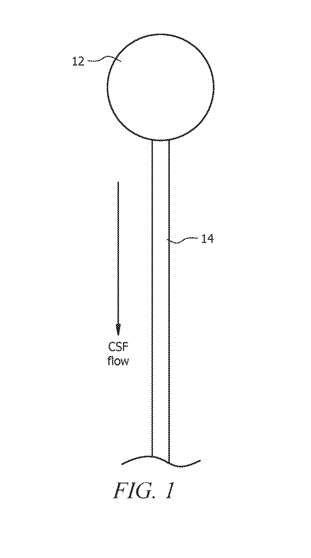
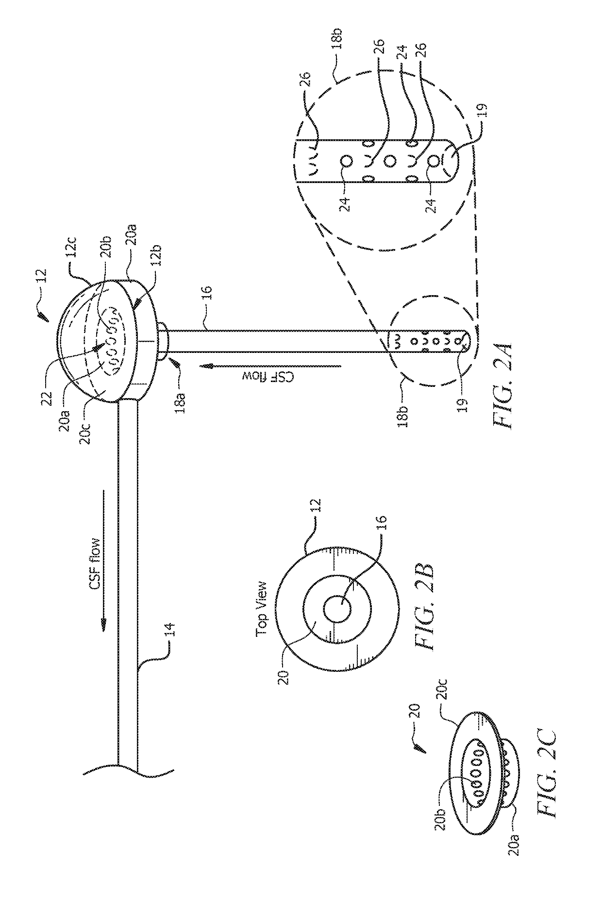
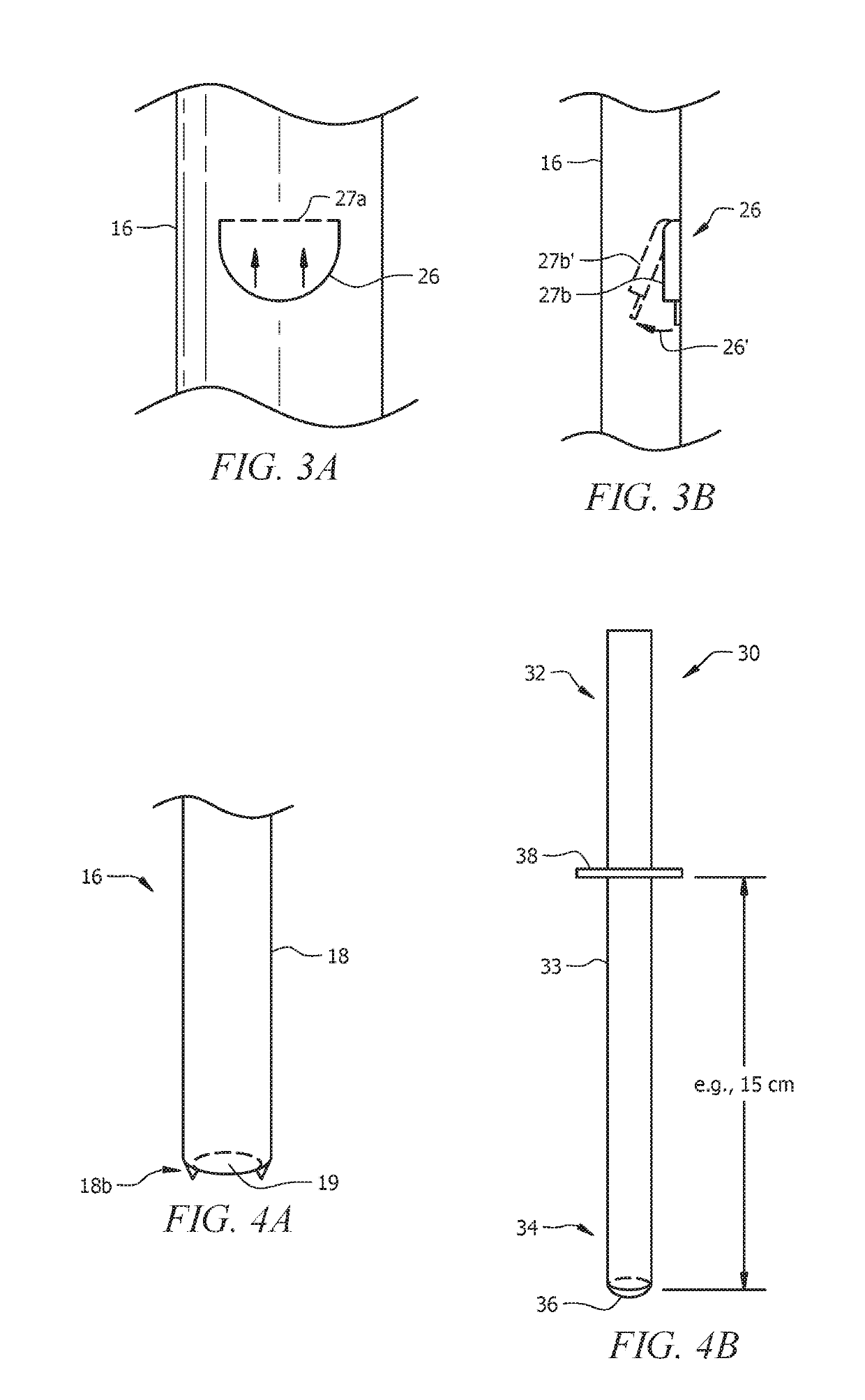
[0050]As seen in FIGS. 1 and 2A-2C, the current invention is a shunt catheter system, generally denoted by the reference numeral 10, that includes reservoir 12, peritoneal catheter 14, open-ended ventricular catheter 16. Ventricular catheter 16 has proximal end 18a and distal end 18b. Distal end 18b of ventricular catheter 16 includes open end 19. Reservoir 12 may include reservoir base 12a having top surface 12b, and flexible dome 12c. Reservoir 12 may further include inline filter 20, which will be described in further detail as this specification continues.

[0051]As used herein, the term “proximal” refers to a relative position closer to a reservoir component of the overall assembly. The term “distal” refers to a relative position further from the reservoir component of the overall assembly. As such, if the goal of the system is to drain cerebrospinal fluid from the brain, for example, the cerebrospinal fluid would travel proximally from the brain to the reservoir component and th...


PUM


Abstract

A shunt catheter system and method of use thereof. The system generally includes an open-ended ventricular catheter with drainage apertures and safety flap valves, a reservoir with inline filter, and a peritoneal catheter. After insertion, for example into the ventricles of the brain, cerebrospinal fluid would pass into the ventricular catheter, through the inline filter in the reservoir, and into the peritoneal catheter, subsequently exiting the shunt catheter system. During insertion of the ventricular catheter, a catheter stylet or wire / string and plug stylet can be positioned therein to occlude the open end. The ventricular catheter may be positioned perpendicular to the peritoneal catheter and can be coupled to one another through the reservoir and inline filter or valve.

Description

CROSS-REFERENCE TO RELATED APPLICATIONS[0001]This nonprovisional application is a divisional of and claims priority to U.S. Nonprovisional patent application Ser. No. 14 / 744,842, entitled “Shunt Catheter System”, filed Jun. 19, 2015 by the same inventor, which claims priority to U.S. Provisional Patent Application No. 62 / 030,946, entitled “Shunt Catheter System with Inline Filter and Method of Use Thereof”, filed Jul. 30, 2014 by the same inventor, both of which are incorporated herein by reference in their entireties.BACKGROUND OF THE INVENTION1. Field of the Invention[0002]This invention relates, generally, to catheters. More specifically, it relates to open-ended shunt catheter systems.2. Brief Description of the Prior Art[0003]Hydrocephalus is one of the most common pathologies encountered in neurosurgery. On average, 6,000 new babies are born with hydrocephalus every year, including two of every 1,000 babies born in the United States, and thousands of people are diagnosed later...

Claims


Application Information

Patent Timeline
Patent Type & Authority Patents(United States)
IPC IPC(8): A61M27/00
CPCA61M27/006A61M2205/7545A61M2205/7563A61M2202/0464A61M2205/75
Inventor BECKMAN, JOSHUA MARSHALL
Owner UNIV OF SOUTH FLORIDA
Why Eureka
Try Eureka