TAVR Ventricular Catheter

a ventricular catheter and ventricular valve technology, applied in the field of ventricular valve catheters, can solve the problems of increasing the potential for heart failure, restricting the blood flow from the heart, and prolonging the procedure duration

Active Publication Date: 2017-01-26
MCDONALD MICHAEL B
View PDF0 Cites 0 Cited by
  • Summary
  • Abstract
  • Description
  • Claims
  • Application Information

AI Technical Summary

Benefits of technology

[0002]Transcatheter aortic valve replacement (TAVR) is a treatment for stenosis of the aortic valve. A stenotic aortic valve is narrowed, restricting blood flow from the heart and increasing the potential for heart failure. TAVR is a minimally invasive approach to implanting an artificial heart valve inside a stenotic aortic valve.
[0004]Proper alignment of the artificial valve within the stenotic aortic valve is critical to the success of the TAVR procedure. The artificial valve should be positioned as exactly as possible on the crushed stenosed valve, parallel with the aortic annulus. Further, correct alignment of the imaging machines used by the cardiologist in relation to the patient's heart valve is critical to achieving the proper alignment of the artificial valve itself. Traditionally, a cardiologist may use high resolution fluoroscopy and / or cineradiography to view the aortic valve. In such imaging, dye is injected into the aorta, causing the valve to be perceived as a somewhat fuzzy white line on the imaging screen. The cardiologist then attempts to position the imaging machine perpendicular to the valve. Because of the innate imprecision of this method, the cardiologist may need to perform multiple x-ray shots (involving the same number of dye injections). This lengthens the duration of the procedure and increases the risk of complications to the patient.

Problems solved by technology

A stenotic aortic valve is narrowed, restricting blood flow from the heart and increasing the potential for heart failure.
This lengthens the duration of the procedure and increases the risk of complications to the patient.

Method used


Image

  • TAVR Ventricular Catheter
  • TAVR Ventricular Catheter
  • TAVR Ventricular Catheter

Examples


Embodiment Construction

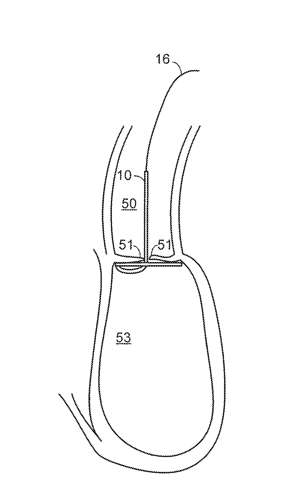
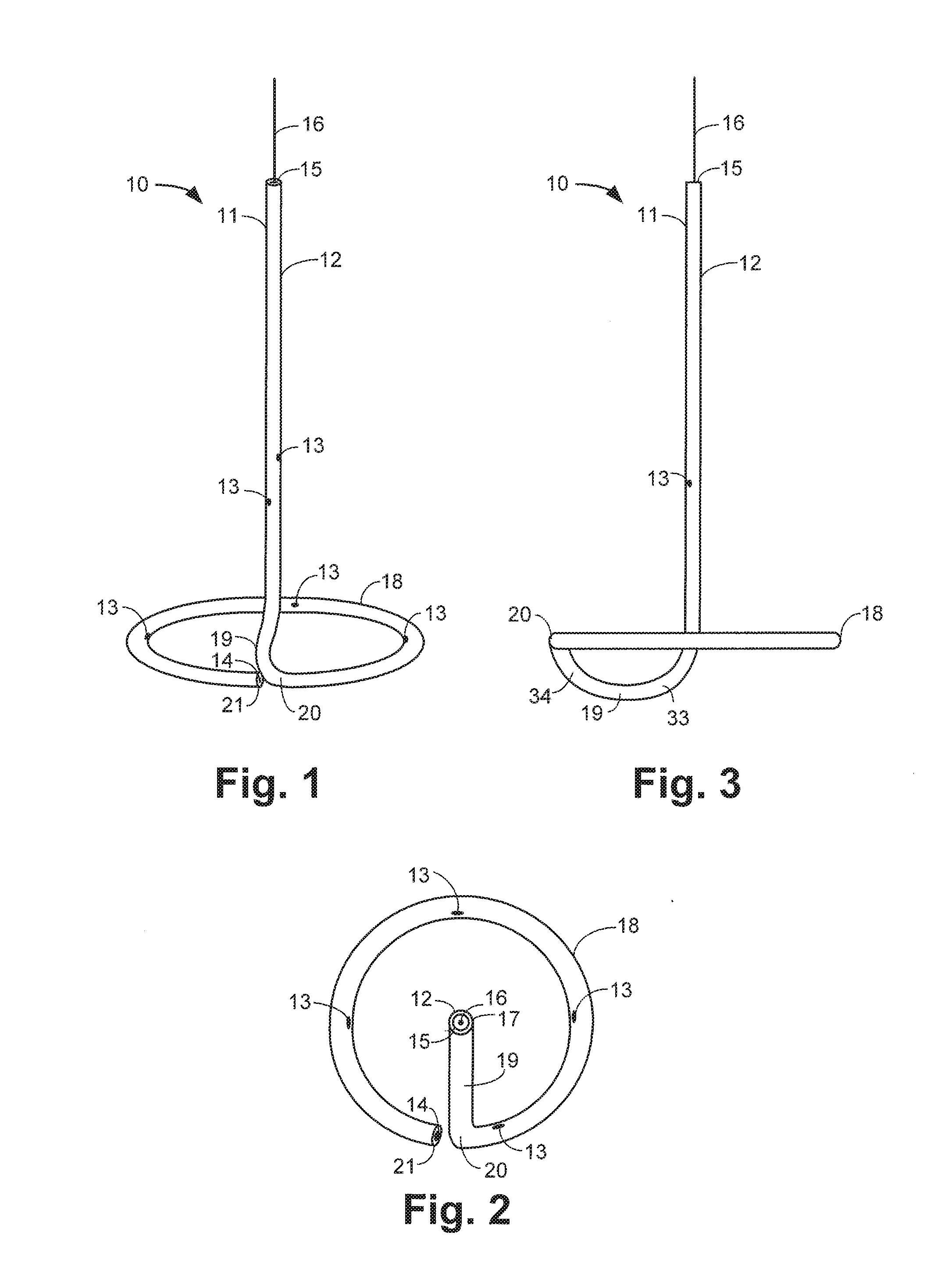
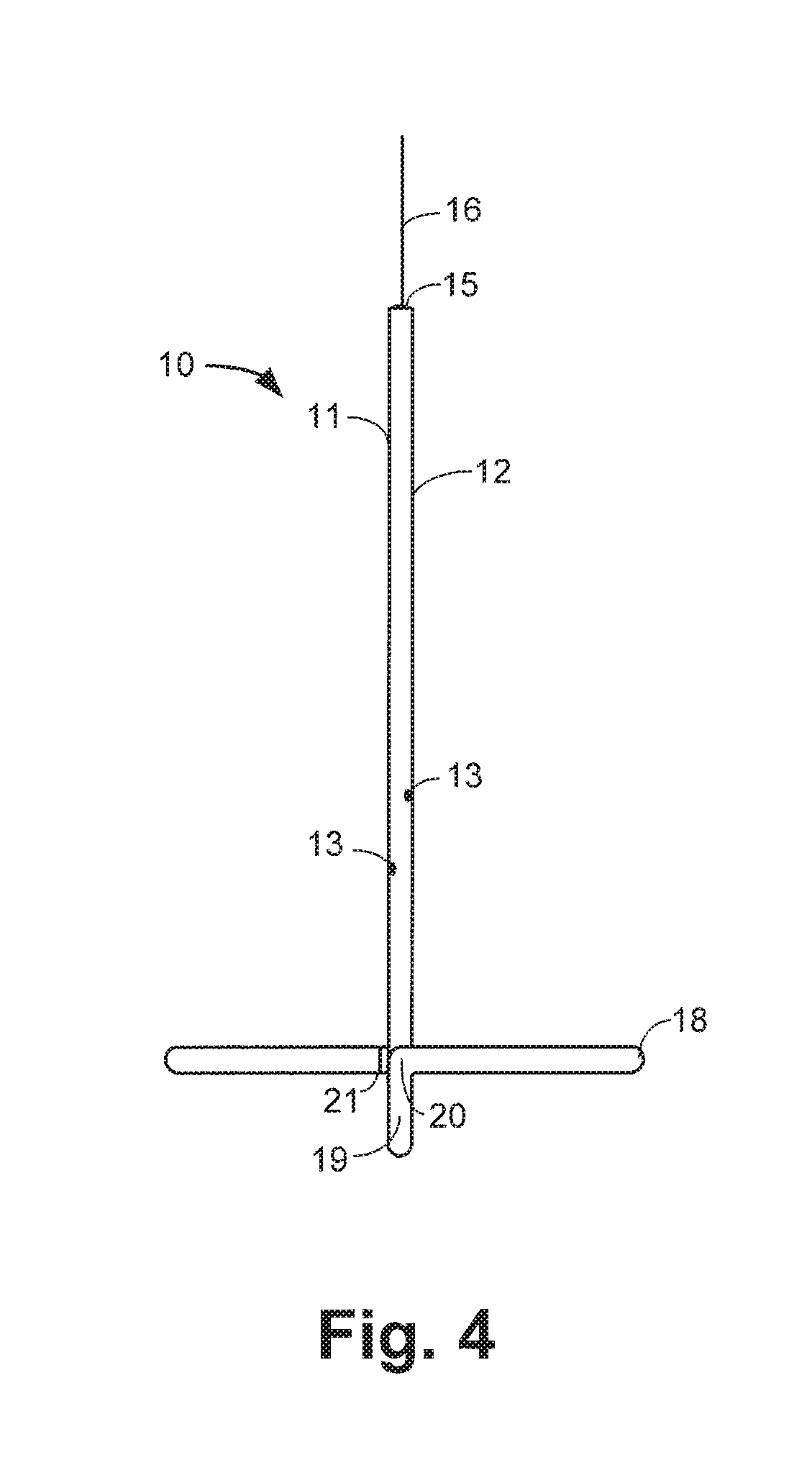
[0017]FIG. 1 is a front perspective view of a TAVR ventricular catheter 10 according to an exemplary embodiment of the present disclosure, with the catheter 10 in its deployed configuration. In this regard, when the catheter 10 is inserted into an aorta (not shown), a guide wire 16 extends completely through the catheter 10. The guide wire 16 is stiffer than the catheter 10, and the catheter 10 is soft and flexible such that the catheter 10 conforms to the shape of the guide wire 16 when the guide wire 16 is extended through the catheter 10. The guide wire 16 is partially withdrawn from the catheter 10 to deploy the catheter 10, which then forms the deployed shape shown in FIG. 1.

[0018]The catheter 10 comprises a hollow cylindrical body 11 with an upper opening 15 and a lower opening 14. The catheter 10 is formed in one piece from a flexible material that is soft enough to conform to the guide wire 16. In one embodiment, the catheter 10 is formed via thin wall extrusion. The opening...


PUM


Abstract

A catheter for positioning a valve during a transcatheter aortic valve replacement is formed from a resilient hollow body conformable to a guide wire when a guide wire is passed in through an upper opening in the hollow body and through the hollow body. When the guide wire is retracted, the catheter deploys to form a substantially straight upper shaft portion that extends downwardly from the upper opening and a distal ring perpendicular to the upper shaft portion. The distal ring approximates the size and shape of the patient's aortic valve annulus. A lower loop connects the upper shaft portion of the catheter to the distal ring. An outer surface of the distal ring is radiopaque, and the distal ring comprises openings for dispersing radio opaque medium used in imaging of the patient's aortic valve annulus. The deployed catheter is retracted until it snugly contacts the aortic valve annulus. The distal ring will be viewed as a straight line when the x-ray C-arm is properly aligned with the aortic valve annulus.

Description

CROSS REFERENCE TO RELATED APPLICATIONS[0001]This application is a continuation of U.S. application Ser. No. 14 / 097,524, filed on Dec. 5, 2013, which claims the benefit of and priority to U.S. Provisional Application Ser. No. 61 / 733,818, titled “TAVR Ventricular Catheter,” filed on Dec. 5, 2012, the entire contents of both of which are herein incorporated by reference.BACKGROUND AND SUMMARY OF THE INVENTION[0002]Transcatheter aortic valve replacement (TAVR) is a treatment for stenosis of the aortic valve. A stenotic aortic valve is narrowed, restricting blood flow from the heart and increasing the potential for heart failure. TAVR is a minimally invasive approach to implanting an artificial heart valve inside a stenotic aortic valve.[0003]During the TAVR procedure, a cardiologist inserts a tube (catheter) through an artery in the groin (transfemoral approach) or a small incision between the ribs (transapical approach). An artificial valve is compressed and fed through the catheter u...

Claims


Application Information

Patent Timeline
Patent Type & Authority Applications(United States)
IPC IPC(8): A61F2/24
CPCA61F2/2427A61F2250/0098A61F2/2496A61B5/1076A61F2230/0091A61M25/0041A61M25/0068A61M25/007A61M25/0074A61M25/0108A61M25/09
Inventor MCDONALD, MICHAEL B.
Owner MCDONALD MICHAEL B
Why Eureka
Try Eureka