Active needle devices with integrated functionality

a technology of integrated functionality and active needles, applied in the field of active needle devices with integrated functionality, can solve the problems of poor mechanical durability, and inability to transmit large amounts of fluid, and achieve the effects of reducing trauma, and reducing the risk of injury

Inactive Publication Date: 2004-09-09
UNIV OF UTAH RES FOUND
View PDF31 Cites 265 Cited by
  • Summary
  • Abstract
  • Description
  • Claims
  • Application Information

AI Technical Summary

Benefits of technology

[0013] In one embodiment of the invention, an active needle device for fluid injection or extraction includes at least one hollow elongated shaft defining at least one channel therethrough. The channel provides communication between at least one input port and at least one output port of the needle device. At least one active component such as a sensor or actuator is placed or integrated into the elongated shaft. The needle device can be a macroneedle, a microneedle, or an array of macroneedles or microneedles. The microneedles can be fabricated on a substrate which can remain attached to the microneedles or can be subsequently removed. The active component can facilitate biochemical, optical, electrical, or physical measurements of a fluid injected or extracted by the needle device.
[0111] The microneedles can be used in a wide variety of biomedical applications. The microneedles can withstand typical handling and can subcutaneously deliver medication without the usual discomfort associated with conventional needles. The microneedles are minimally invasive, in that the microneedles only penetrate just beyond the viable epidermis, reaching the capillaries and minimizing the chance of encountering and damaging the nerves present in the area of penetration.

Problems solved by technology

Most of the prior systems do not have the capability to transmit larger amounts of fluid into a precise location.
Problems with prior microneedles include relatively poor mechanical durability.
This is mainly due to the fact that such microneedles have been made out of etched silicon or out of chemical vapor deposited polysilicon, both of which have a tendency to be brittle and break easily.
In these cases, having a separate analysis system can require additional equipment and is costly, complex, and inconvenient.

Method used


Image

  • Active needle devices with integrated functionality
  • Active needle devices with integrated functionality
  • Active needle devices with integrated functionality

Examples


example 2

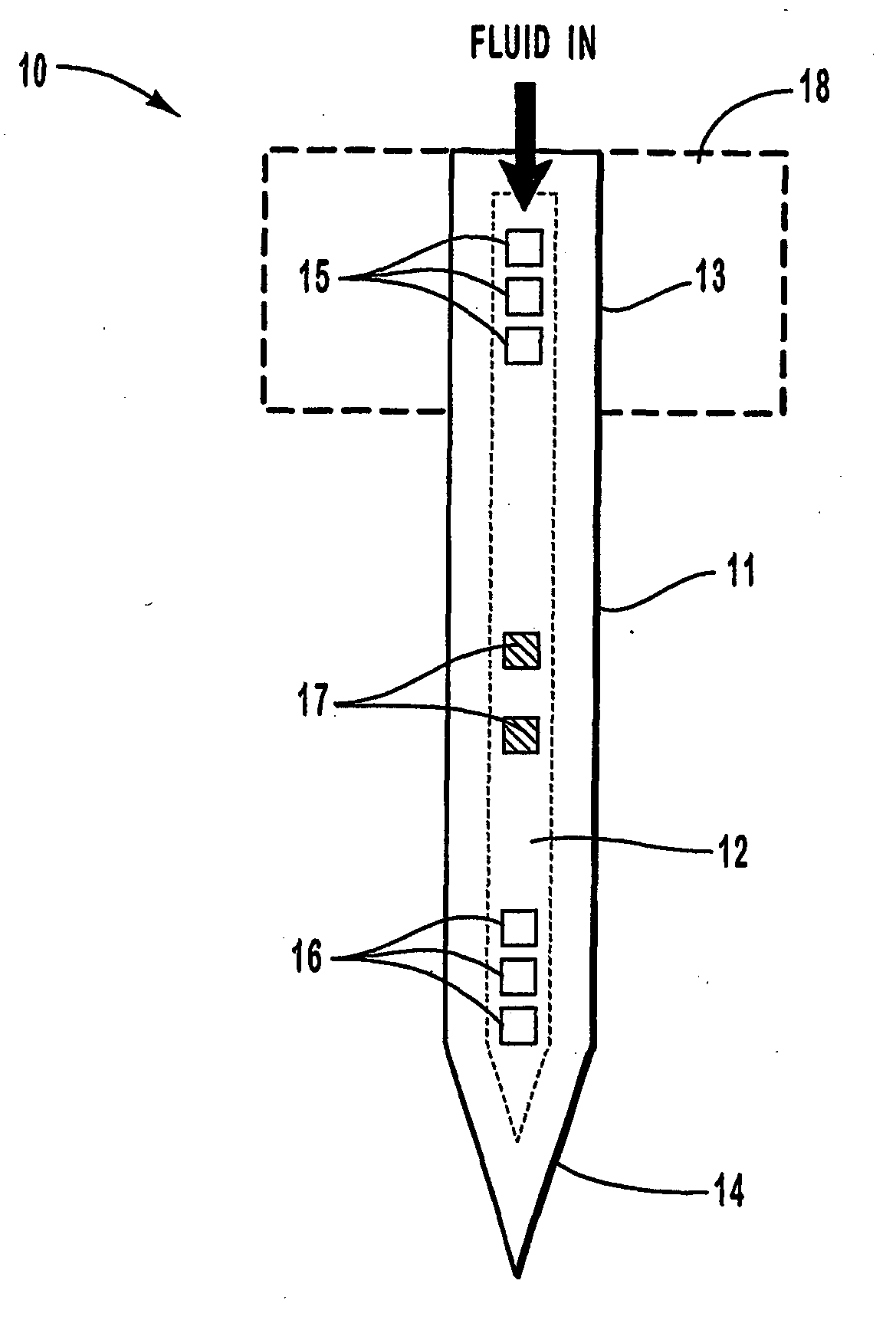
[0116] Individual hollow metallic microneedles were fabricated with multiple output ports and had an inner cross-sectional area of 140.times.21 .mu.m.sup.2 (width by height) with outer cross-sectional area dimensions of 200.times.60 .mu.m.sup.2. The tip dimensions of the microneedles were less than 15.times.15 .mu.m.sup.2. The length of the tapered portion of the needle shaft was 1 mm and the distance from the tip to the first output port was about 300 .mu.m. The total length of each microneedle was 6 mm, with input port inner dimensions of 140 .mu.m wide and 21 .mu.m high. The wall thickness of each microneedle was about 20 .mu.m, and the output ports were formed with dimensions of 30 .mu.m.sup.2 on the top and bottom of the microneedles. The output ports were separated by 30 .mu.m, and there were 9 ports on the top and 12 ports on the bottom of each microneedle.

[0117] The microneedles were each packaged into a standard Luer-lock fitting using a polymeric medical grade UV-curable a...

example 3

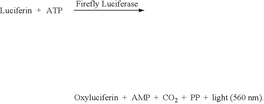
[0118] A preliminary experiment was conducted to assay a glucose via glucokinase and firefly luciferase reactions. The assay was a homogeneous ATP depletion type assay with initial concentrations of glucokinase (80 nano-molar), ATP (10 micro-molar), luciferin (100 micro-molar), and firefly luciferase (0.1 nano-molar) in 0.45 M glycyl glycine buffer at pH 7.8. The results are shown in the graph of FIG. 11, which plots the normalized luminometer bioluminescence, detected two minutes after the rapid mixing of all reactants, as a function of initial glucose concentration. The results suggest that a single step homogeneous assay for glucose can be accomplished without initial dilution of the glucose in the sample.

example 4

[0119] FIGS. 12 and 13 are graphs showing the characteristics for a creatine biosensor. The graph of FIG. 12 plots the normalized bioluminescent signal (in relative light units) as a function of time for several different concentrations of creatine. The bioluminescent signal had a 560 nm wavelength and was measured by a luminometer. The final concentrations of creatine shown are within the physiological serum creatine concentration range.

[0120] FIG. 13 shows the results of an assay experiment for creatine using the creatine kinase and firefly luciferase reactions. The creatine assay was a homogeneous ATP depletion assay (the creatine kinase reaction competes with the firefly luciferase reaction for the ATP). The final assay constituents were buffered in 0.45 molar glycine-glycine buffer at pH 7.8 and the final assay concentrations were the following: 1.4 .mu.M ATP, 71 .mu.M Mg.sup.2+, 14 .mu.M luciferin, 0.3 .mu.M luciferase, 60 .mu.M creatine kinase, and various concentrations of c...


PUM


Abstract

An active needle device (10) for fluid injection or extraction includes at least one hollow elongated shaft (11) defining at least one channel (12). The channel (12) provides communication between at least one input port (15) and at least one output port (16) of the needle device (10). At least one active component (17) such as a sensor or actuator is placed or integrated into the elongated shaft (1 1). The needle device (10) can include a macroneedle, a microneedle (21), or an array of macroneedles or microneedles (25a). The microneedles (21) can be fabricated on a substrate (26) which can remain attached to the microneedles (21) or be subsequently removed. The active component can facilitate biochemical, optical, electrical, or physical measurements of a fluid injected or extracted by the needle device (10).

Description

[0001] 1. Field of the Invention[0002] The present invention relates generally to needle devices for the injection and extraction of fluids. More specifically, the present invention relates to active needle devices such as macroneedles, microneedles, and macroneedle or microneedle arrays which have one or more active components providing additional functionality to the needle devices.[0003] 2. Relevant Technology[0004] Micro instrumentation is a rapidly growing area of interest for a broad spectrum of applications. One particularly fast growing area is biomedical instrumentation where significant efforts are being made to develop micro biochemical analysis systems, physiological analysis systems, and drug delivery systems. A variety of manufacturing technologies are used to fabricate these micro systems, many of which are categorized under the set of technologies known as micromachining. The number of biomedical applications for micromachining technologies is rapidly growing. Since ...

Claims


Application Information

Patent Timeline
Patent Type & Authority Applications(United States)
IPC IPC(8): A61M37/00
CPCA61M37/0015A61M2037/0053A61M2037/0038A61M2037/003
Inventor FRAZIER, A BRUNOANDRADE, JOSEPH D.BARTHOLOMEUSZ, DANIEL A.BRAZZLE, JOHN D.
Owner UNIV OF UTAH RES FOUND
Why Eureka
Try Eureka