Tool jig for bone implant assembly

a bone implant and tool jig technology, applied in the field of medical implants, can solve the problems of inability to precisely position and orientation the pre-drilling and inability to precisely drill the hole in the bon

Inactive Publication Date: 2011-05-05
AUSTOFIX GRP
View PDF7 Cites 80 Cited by
  • Summary
  • Abstract
  • Description
  • Claims
  • Application Information

AI Technical Summary

Benefits of technology

[0020]In an embodiment, at least one of the tool jig apertures further guides placement of an outer sleeve within the tool jig aperture, wherein the outer sleeve further guides placement of the drill sleeve within the fixing element aperture. Preferably, the outer sleeve is also a tool that enables separation of the tool jig from the bone plate.

Problems solved by technology

However, it is difficult to pre-drill holes in bone in precisely the right position and orientation.
However, surgeons may need to hold a drill jig in place manually, resulting in inaccuracies in alignment of the drill jig and the bone plate.
However, it is still difficult to drill a hole into bone on the desired angle using these drill jigs fixed to the bone plate, as such drill jigs permit some inaccuracies in alignment of the drill or drill sleeve, for example, permitting flexibility in the angle of the drill or drill sleeve, or possibly resulting in cross threading of the drill hole when the fixing element is inserted.

Method used


Image

  • Tool jig for bone implant assembly
  • Tool jig for bone implant assembly
  • Tool jig for bone implant assembly

Examples


Embodiment Construction

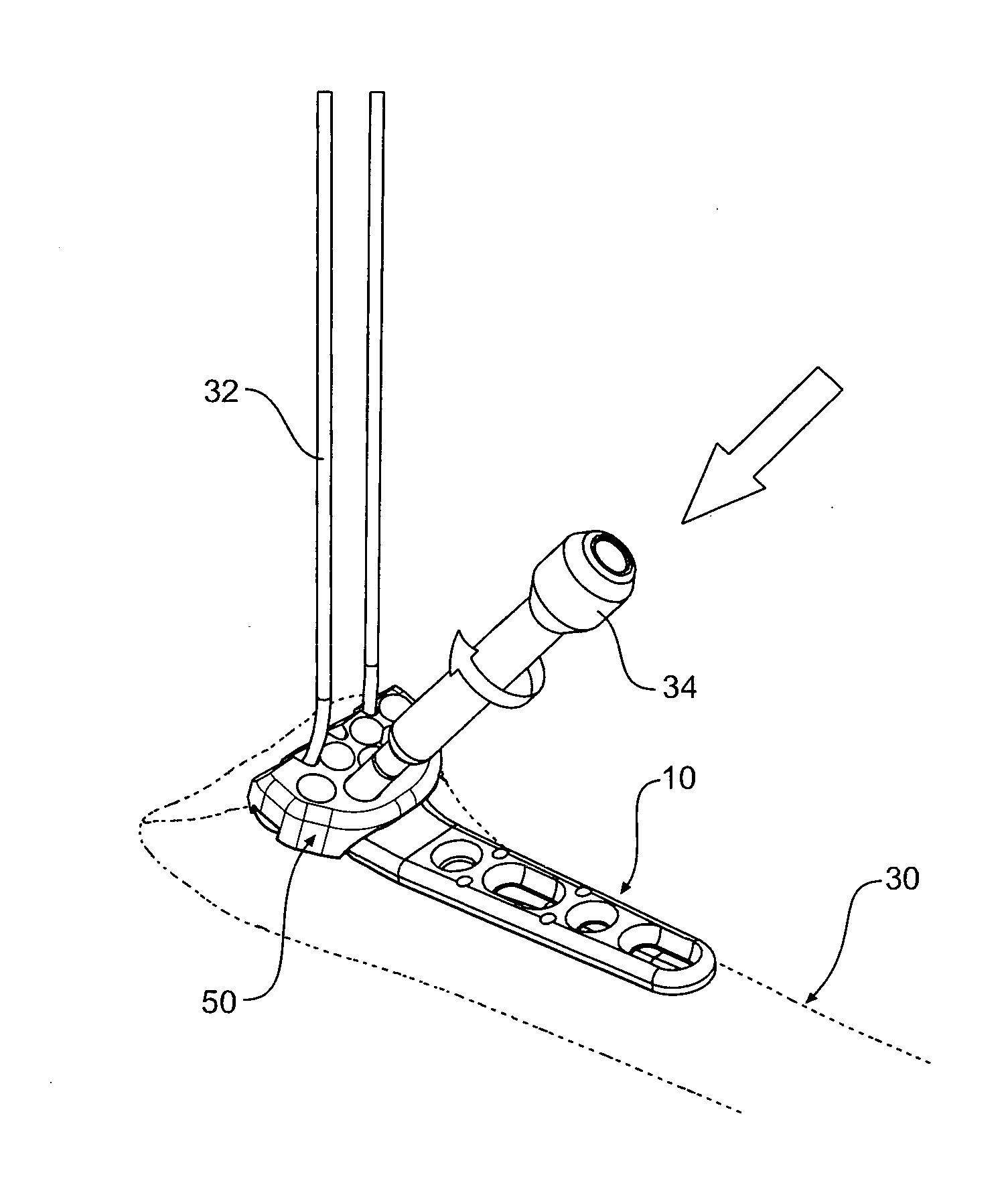
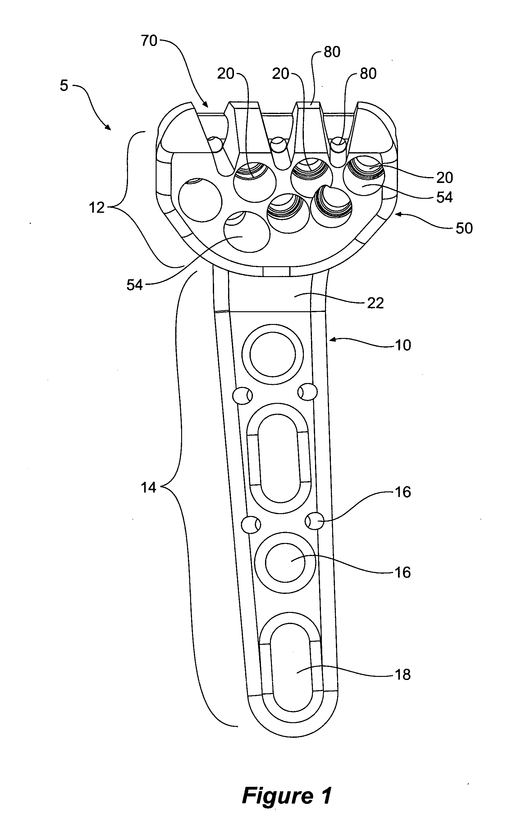
[0069]Referring to FIG. 1, there is shown a medical implant assembly 5 comprising a tool jig 50 which is releasably secured to a bone plate 10. The bone plate 10 consists of a head portion 12 and tail portion 14 encompassing a plurality of fixing element apertures 16,18,20. In use, fixing elements are inserted through the fixing element apertures into underlying bone 30 to fix the bone plate 10 to bone 30. The fixing element apertures 16,18,20 are located in predetermined positions and set at predetermined angles to enable fixing elements 32, 36 to be placed into the bone 30 in positions and angles that, together with the bone plate 10, optimally enhance healing of a fractured or broken bone. The fixing elements 32,36 may engage bone fragments, fractured bone or non-fractured bone. The fixing element apertures 16,18,20 within the bone plate 10 are elongate fixing element apertures 18 or circular fixing element apertures 16,20 and are sized to fit a range of fixing elements such as b...


PUM


Abstract

The invention provides a tool jig (50) for use with a bone plate (10) having one or more fixing element apertures (20), wherein the tool jig (50) guides placement of a drill sleeve (34) to enable the drill sleeve (34) to be attached to a fixing element aperture (20), the tool jig (50) comprising a body (52), a securing means (80) on the body adapted to releasably secure the tool jig (50) to the bone plate (10) such that the tool jig (50) can be firstly secured in position to the bone plate (10) and secondly removed, and one or more tool jig apertures (54) defined in the body (52) wherein an at least one or all tool jig apertures (54) are adapted to be substantially aligned with an at least one or all fixing element apertures (20); wherein, in use, the tool jig aperture (54) guides the drill sleeve (34) so that the longitudinal axis of the drill sleeve (34) substantially aligns with the axis of the fixing element aperture (20) prior to attaching the drill sleeve (34) to the fixing element aperture (20). The invention also provides a medical implant assembly (5) comprising the tool jig (50) and the bone plant (10), a kit comprising the medical implant assembly and at least one drill sleeve (34), and methods of using same.

Description

FIELD OF THE INVENTION[0001]The present invention relates to a medical implant assembly. In particular, the invention relates to a medical implant assembly that is fixed to bone. In a particular embodiment, the invention relates to a tool jig for a bone implant assembly.PRIORITY DOCUMENTS[0002]The present application claims priority from Australian Provisional Patent Application No. 2008901592 titled “Medical Implant Assembly” and filed on 3 Apr. 2008.BACKGROUND OF THE INVENTION[0003]It is advantageous that a fractured bone is stabilised as quickly as possible to achieve adequate healing of a fracture. To this end, implantable bone plates can be utilised to hold a fractured bone in an optimised position to enhance healing. The bone plate can be firmly fixed to the bone in the vicinity of the fracture site by means of screws and other fixing elements that pass through a bone plate aperture, for example, utilising a series of preformed holes drilled into the bone prior to bone plate i...

Claims


Application Information

Patent Timeline
Patent Type & Authority Applications(United States)
IPC IPC(8): A61B17/80A61B17/56
CPCA61B17/1721A61B2017/1782A61B17/1728A61B17/1782
Inventor LAIRD, EWEN
Owner AUSTOFIX GRP
Why Eureka
Try Eureka