Electric connector

a technology of electrical connectors and connectors, which is applied in the direction of electrical equipment, substation/switching arrangement details, coupling device connections, etc., can solve the problems of inability to reliably prevent the movement of the terminal in the wall opening, the loss of one component of the terminal made in several parts, and the inability to lock. , to achieve the effect of improving the mounting element and simple geometry

Inactive Publication Date: 2009-04-16
PHOENIX CONTACT GMBH & CO KG
View PDF13 Cites 8 Cited by
  • Summary
  • Abstract
  • Description
  • Claims
  • Application Information

AI Technical Summary

Benefits of technology

[0016]The electrical terminal in accordance with the invention is advantageous in many respects. The elastic clamping element makes it possible to close tolerances between the inside edge of the narrow side of the wall opening and the terminal housing, the comparable play between the terminal and the inside edge of the wall opening being determined by the maximum spring path of the elastic clamping element. In addition to this purely geometrical compensation of play, the elastic clamping element moreover also causes fixing of the terminal in the wall opening of the housing wall in the direction of this inside edge of the wall opening. At the same time the elastic clamping element also fixes the terminal in the wall opening in the joining direction and in the direction opposite the joining direction, i.e. perpendicular to the actual main clamping direction.
[0017]The terminal in accordance with the invention can be further improved with respect to its fixing in the opening of the housing wall by the elastic clamping element having an arched or oblique clamping surface and the clamping surface for its part having several ribs which run parallel to one another. In the installed state of the terminal then at least one rib forms teeth depending on the thickness of the housing wall with the inside edge of the wall opening. In this way the terminal can be fixed in the wall opening of housings with different wall thickness. The extension of the arched or oblique clamping surface in the joining direction of the terminal defines the maximum thickness of the housing wall with which the elastic clamping element can interact so that the desired catch action with the inside edge of the wall opening is achieved.
[0018]The terminal in accordance with the invention can be developed especially advantageously with respect to its locking in the opening of the housing wall by the mounting element having an actuating wedge which is located with a swivelling or pivoting capacity on the mounting element such that it can be pivoted into the position in which the elastic clamping element in the mounted state of the terminal is pressed by the actuating wedge against the corresponding inside edge of the wall opening. The actuating wedge can be fixed in this position so that the location of the elastic clamping element in the installed state of the terminal can also be permanently maintained.
[0020]So that this deflection is permanently maintained in the mounted state, the actuating wedge must remain in the described position. This is advantageously achieved in that teeth are formed on the surface of the actuating wedge and on the side of the fixing element facing the surface of the actuating wedge opposing teeth which correspond thereto are formed. This configuration of the actuating wedge thus provides for reliable fixing of the terminal in the opening of the housing wall by the elastic spring element being pressed against the inside edge of the wall opening and being held at the same time in its installation position.
[0023]A further improvement of the mounting element can be achieved in that the free end of the catch tongue has an arched or oblique clamping surface which points to the outside and several ribs which run parallel to one another are formed on the clamping surface. This improved configuration enables the mounting element to interact reliably with the inside edge of the opening in the housing wall and the electrical terminal to be reliably fixed in the wall opening.
[0024]According to another embodiment of the mounting element, an actuating wedge is arranged to be able to pivot on the free end of the U-leg. The actuating wedge can be swivelled into a position such that it presses the elastic clamping element in the mounted state of the terminal against the corresponding inside edge and thus provides for reliable fixing of the terminal in the wall opening. Thus the elastic clamping element can be deflected by the actuating wedge against its spring force, by which the terminal in the mounted state is fixed in the wall opening.

Problems solved by technology

The disadvantage in the described attachment possibilities under certain circumstances can be major mounting problems which arise solely by the housing wall having to be accessible on both sides, therefore from the inside of the housing and also the outside of the housing.
Furthermore, for only poorly accessible mounting sites there is the danger that one component of the terminals which is made in several parts can be lost.
However, the disadvantage here can also be that locking takes place only with two opposing edges of the wall opening.
This results in that in the presence of a tolerance between the electrical terminal and the wall opening, movement of the terminal in the wall opening cannot be reliably prevented.

Method used


Image

  • Electric connector
  • Electric connector
  • Electric connector

Examples


Embodiment Construction

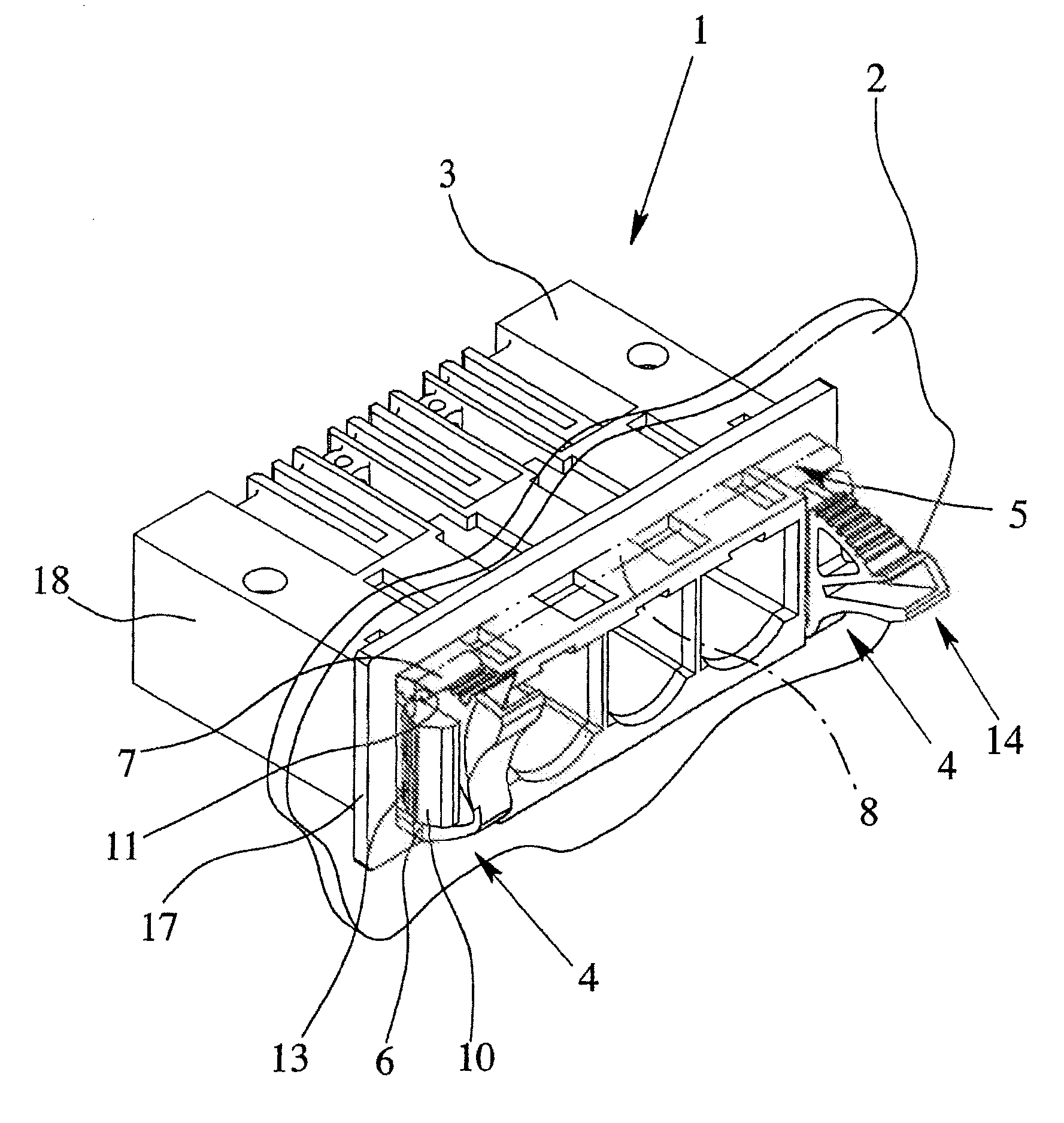
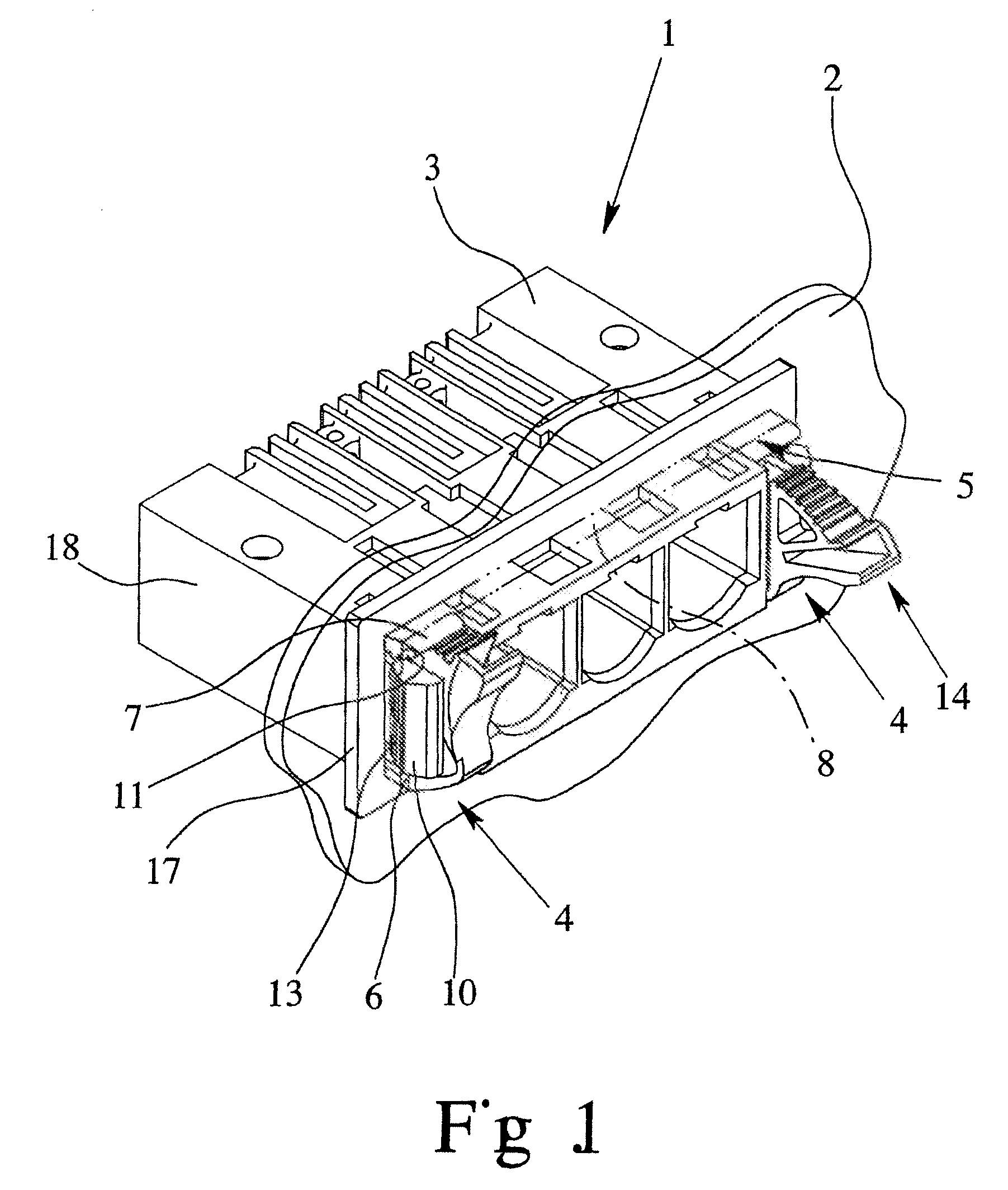
[0029]FIG. 1 shows an electrical terminal 1 for routing a line through the housing wall 2. The terminal 1 has a rectangular terminal housing 3 of insulating material with—in this specific embodiment—three connecting elements, the connecting elements adjoining and on two ends being bordered by one mounting element 4 at a time for fixing the terminal 1 in a likewise rectangular wall opening 5. The number of connecting elements of the terminal 1 is completely irrelevant to the teaching underlying the electrical terminal in accordance with the invention; one preferred embodiment has fewer, but also more terminal elements could have been shown equally well. In particular, several disk-shaped terminals 1 with one terminal element each can also be joined into a terminal block, then the terminal block having altogether one mounting element 4 each on two sides.

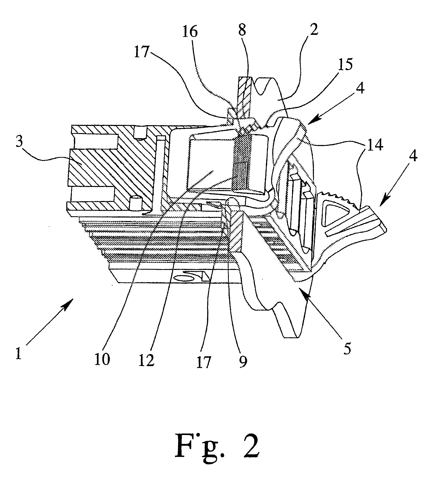
[0030]The mounting element 4 which is shown isolated in FIG. 3 has two fixing elements 6, 7 which in the mounted state of the termina...


PUM


Abstract

An electric connector for passing a line through a housing wall has a rectangular housing made of an insulating material, at least one connection element and a securing element used to secure the connector to the rectangular wall opening of the housing wall. The securing element includes at least one fixing element and an elastic clamping element which is arranged in an essentially perpendicular manner in relation to the fixing element, such that the clamping element interacts against an inner edge of the narrow side of the wall opening when the connector is in the mounted state.

Description

BACKGROUND OF THE INVENTION[0001]1. Field of the Invention[0002]The invention relates to an electrical terminal for routing a line through a housing wall, with a rectangular terminal housing of insulating material, with at least one connecting element and with a mounting element for fixing the terminal in a rectangular wall opening of the housing wall, the mounting element having at least one fixing element. In addition, the invention relates to a mounting element for fixing an electrical terminal in the wall opening of a housing wall, with at least one fixing element.[0003]2. Description of Related Art[0004]Electrical terminals or electrical connectors for routing a line through a housing wall are often also called bushing terminals or bushing connectors. Both one-part and also two-part bushing terminals are known. In the two-part bushing terminals one part of the terminal is mounted in the housing wall opening, while the other part is electrically and mechanically connected to the...

Claims


Application Information

Patent Timeline
Patent Type & Authority Applications(United States)
IPC IPC(8): H01R13/73
CPCH01R13/6273H01R13/745H01R13/743
Inventor GIEFERS, STEFAN
Owner PHOENIX CONTACT GMBH & CO KG
Why Eureka
Try Eureka