Locking device

A technology of locking device and locking part, which is applied in the direction of quick-action fasteners, etc., can solve the problems of potential safety hazards, tool movement up and down, affecting the processing effect, etc., and achieve the effect of improving the relative fixation

Inactive Publication Date: 2011-06-15
贺发民
View PDF0 Cites 8 Cited by
  • Summary
  • Abstract
  • Description
  • Claims
  • Application Information

AI Technical Summary

Problems solved by technology

When the tool is processing food, the tool rotates to generate axial force, and the tool will move up and down, which not only affects the processing effect, but also poses a safety hazard

Method used


Image

  • Locking device
  • Locking device

Examples


Embodiment Construction

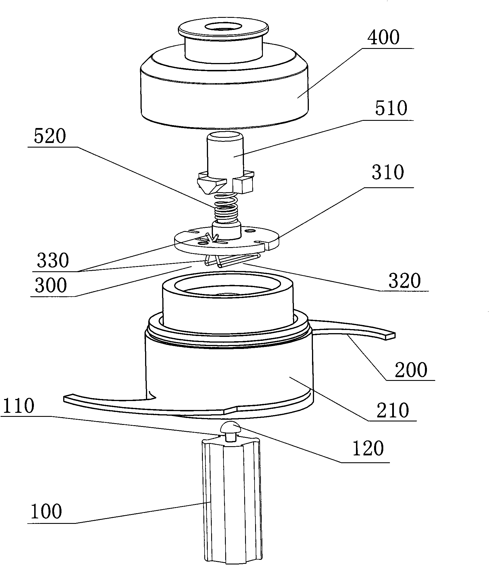
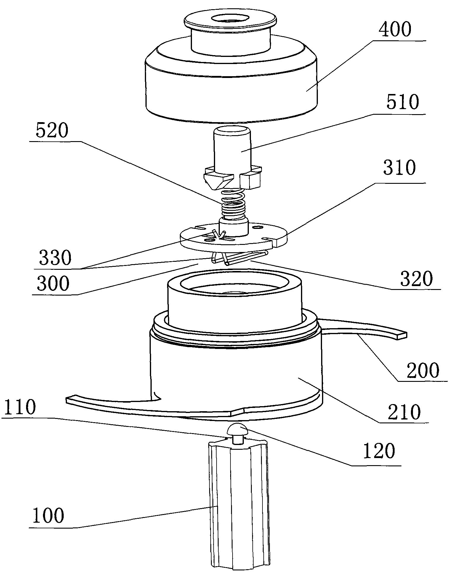
[0015] Such as figure 1 As shown, a locking device, specifically a knife locking device for a kitchen food mixer, includes a shaft, that is, a transmission shaft 100, and also includes a target part, that is, a knife 200. A locking groove 110 is provided on the transmission shaft 100, and the transmission The top 120 of the shaft 100 is a mushroom-shaped arc surface; it also includes a lock spring 300 matching the lock groove 110, the cutter 200 is arranged on the fixed frame 210, an upper cover 400 is arranged on the fixed frame, and the lock spring 300 is arranged on On the lock spring frame 310 , the lock spring frame 310 is embedded in the fixed frame 210 , so that the lock spring frame 310 is connected with the fixed frame 210 . The lock spring 300 is "L"-shaped, including a "U"-shaped locking part 320 at the bottom and an "X"-shaped fixing part 330 standing upright on the side. By opening the fixing part 330, the locking part 320 can also be opened. , the locking portio...


PUM


Abstract

The invention discloses a locking device which comprises a shaft and a target piece, wherein the shaft is provided with a locking groove; the target piece is provided with a locking spring which is matched with the locking groove; when in mounting, the locking spring is clamped in the locking groove, the locking spring locks the locking groove tightly through a tightened elastic force, thus the fixation of the target piece and the shaft is realized; and when in dismounting, the locking spring is unfolded through the external force, the locking groove is loosened by the locking spring, and the separation of the target piece and the shaft is realized. Compared with the prior art, the locking device provided by the invention has the advantages that because of the design of the locking groove and the locking spring, the defects of the prior art are overcome, the relative fixation of the target piece and the shaft can be improved effectively, and the rapid mounting and dismounting of the target piece can be realized.

Description

technical field [0001] The invention relates to a locking device, in particular to a locking device used on a rotating shaft, such as a locking device for fixing knives on the rotating shaft in various food cooking machines. Background technique [0002] In the prior art, it is necessary to relatively fix certain target parts on the shaft so as to realize detachable installation of the fixing parts and relative fixation to the shaft. Taking food processing equipment as an example, with the continuous improvement of people's living standards, food processing equipment such as mixers, juicers, meat grinders and food processors are more and more widely used, such as in home kitchens, restaurants, juice bars and other occasions. The food processing equipment in the prior art usually includes a main machine with a motor, a transmission shaft driven by the motor, and a cutter driven by the transmission shaft, and the cutter is the target object. [0003] The technical defect of ...

Claims


Application Information

Patent Timeline
Patent Type & Authority Applications(China)
IPC IPC(8): F16B21/07
Inventor 贺发民
Owner 贺发民
Why Eureka
Try Eureka