Interlaminar Stabilizing System

Active Publication Date: 2011-05-05
PIONEER SURGICAL TECH INC
View PDF65 Cites 76 Cited by
  • Summary
  • Abstract
  • Description
  • Claims
  • Application Information

AI Technical Summary

Benefits of technology

[0006]In accordance with one form, a spinal stabilization system includes a first engagement member and support structure therefor. The first engagement member is adapted to be disposed between a first vertebra and a second vertebra. The engagement member generally includes a recess or saddle such as in the form of a generally concave seating surface configured for receiving at least a portion of

Problems solved by technology

Because of the configuration and location of the spinous processes relative to the remainder of the vertebra, the moment generated by these systems can potentially cause misalignment of the corresponding vertebrae relative to the rest of the spine.
Accordingly, the interspinous spacer systems rely on the integrity of the spinous processes, which can become brittle or unreliable due to aging or other factors.
Such systems, alone, are incapable of minimizing reduction

Method used


Image

  • Interlaminar Stabilizing System
  • Interlaminar Stabilizing System
  • Interlaminar Stabilizing System

Examples


first embodiment

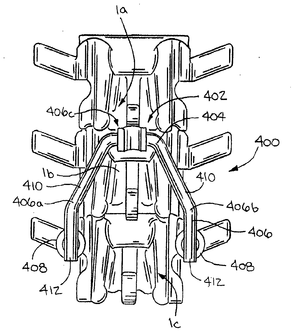
[0195]Turning to FIGS. 70-73, a twenty-first embodiment of the spinal stabilization system is illustrated in the form of an assembly 2102 of at least two spacer members 2104 joined by a connector 2106. Preferably, the connector is a resilient member that permits some movement between the individual spacer members 2104 as the connector 2106 resiliently flexes. By one approach, each of the spacer members 2104 is generally similar to the previous described spacer members 2004; therefore, only the differences therefrom will be described further.

[0196]As best illustrated in FIGS. 72-73, the assembly 2102 includes the two spacer members 2104a and 2104b joined by the connector 2106 in the form of a thin, resilient connecting strip (such as a titanium or other biocompatible material) that is secured to and extends between the two spacer members 2014a and 2104b. A pair of fasteners 2108 are provided to secure the connector 2106 to each spacer member 2104a and 2104b so that the spacer members...

second embodiment

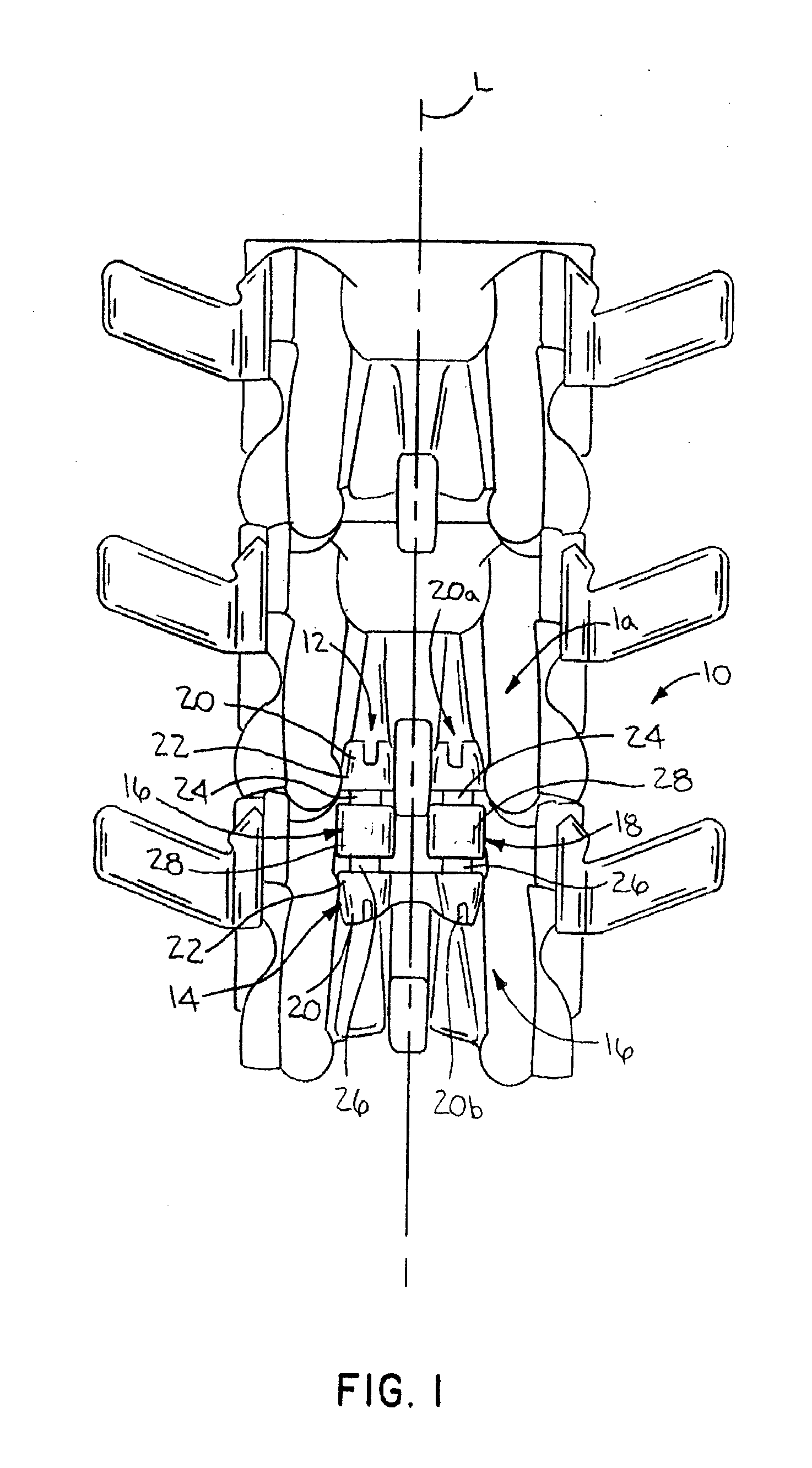
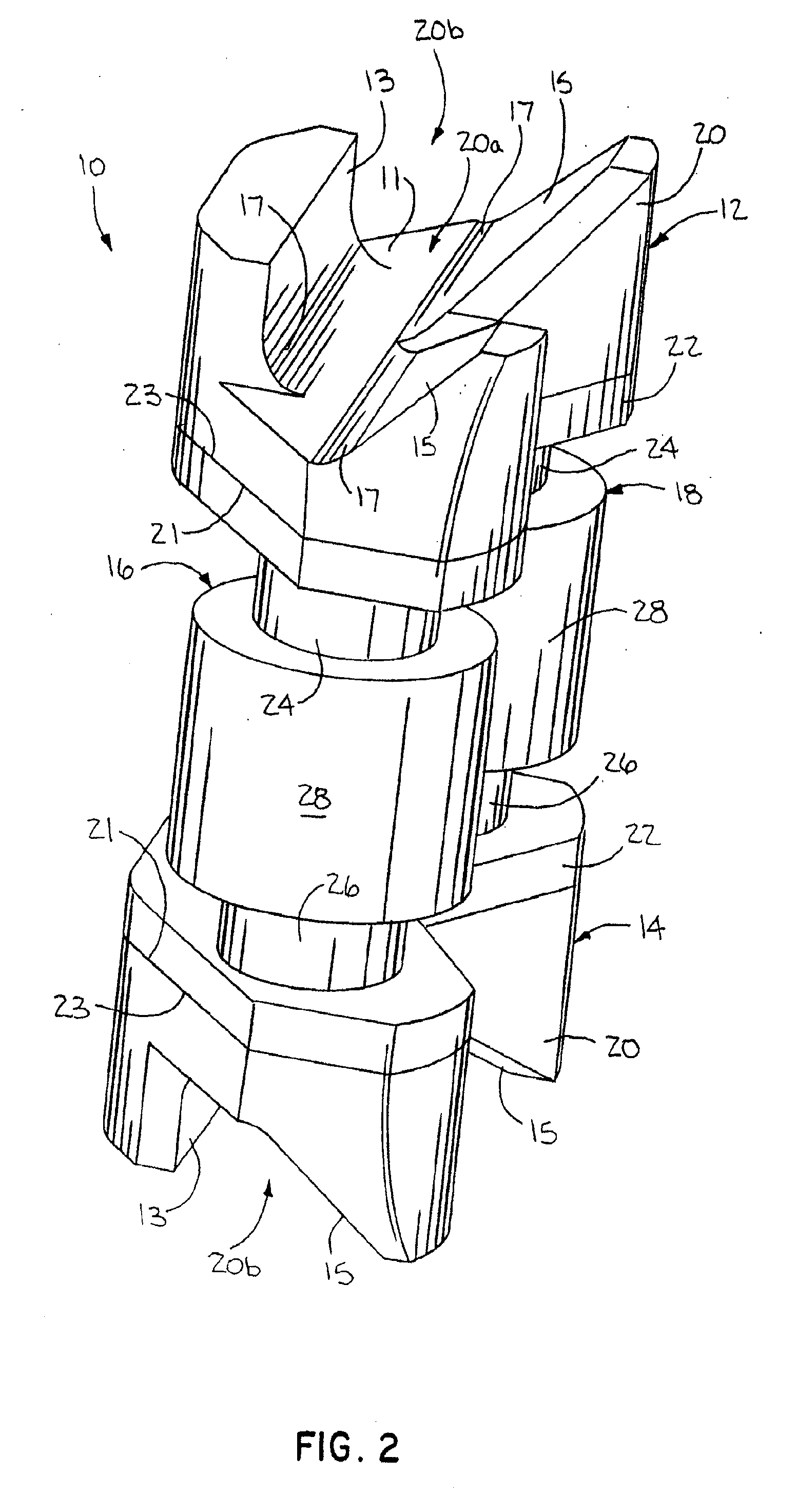
[0200]Referring to FIGS. 74-81, a twenty-second embodiment of a spinal stabilization system 2202 is illustrated in the form of a unitary laminar spacer 2204 having a configuration that permits it to be inserted from a lateral approach and then pivoted into position where it is wedged between the laminar regions 11 of adjacent vertebrae as shown in FIGS. 75-77. The laminar spacer 2204 may be formed from any resilient-type material, such as polyurethane and the like, or from a more rigid material, such as PEEK or the like. While the spacer 2204 is illustrated as a generally solid member, if formed from a more resilient material, it can optionally include an actuator or adjustment device to shift the spacer 2204 from a compressed to an expanded or distracted configuration similar to that found on the embodiments shown in FIG. 47 (spacer member 1504) or FIG. 58 (spacer member 1804).

[0201]As best shown in FIGS. 77-79, the laminar spacer 2204 has a configuration that provides for the pref...

third embodiment

[0204]Referring to FIGS. 82 to 84, a twenty-third embodiment of a laminar stabilization assembly 2302 is illustrated in the form of a laminar spacer 2304 having an articulating connection 2306 between a superior laminar spacer 2304a and an inferior laminar spacer 2304b. In one form, the articulating connection 2306 includes a cooperating ball and socket joint. As best shown in FIG. 84, the assembly 2302 includes multiple components. For instance, it preferably includes the superior laminar spacer or a superior laminar bra 2304a, a socket portion 2308 joined to the superior laminar spacer 2304a, the inferior laminar spacer or an inferior laminar bra 2304b, a dome or ball portion 2310 joined to the inferior laminar spacer 2304b, a spherical washer 2312, an inside washer 2314, an outside washer 2316, and an fastener 2318 to secure the assembly together.

[0205]Similar to the previously described embodiments, the superior laminar spacer 2304a and the inferior laminar spacer 2304b have sem...


PUM


Abstract

A spinal stabilization system includes a first engagement member and a support structure. The first engagement member is adapted to be disposed between a first vertebra and a second vertebra. The engagement member generally includes a seating surface for accommodating at least a portion of a laminar region of the first vertebra. The support structure engages a portion of the second vertebra. The structural cooperation of the first engagement member and the support structure is such that the engagement member restricts reduction of the intervertebral spacing between the first and second vertebrae.

Description

FIELD OF THE INVENTION[0001]The present invention relates generally to a spinal stabilization system and, more particularly, a spinal stabilization system for limiting either distraction or reduction of the intervertebral spacing between adjacent vertebrae.BACKGROUND OF THE INVENTION[0002]Many conventional spinal stabilization systems may be categorized as including interspinous support systems, laminar hook systems, longitudinal rod systems or some combination thereof. Interspinous support systems generally include a spacer disposed between and directly engaging adjacent spinous processes. The spacer may include seating surfaces that are contoured or configured to fittingly engage or receive the opposing spinous processes, thereby maintaining the axial and / or lateral disposition of the spacer relative thereto. Such interspinous spacers provide a support structure adapted to reduce or limit any reduction in the intervertebral spacing between the adjacent vertebrae. Typical laminar h...

Claims


Application Information

Patent Timeline
IPC IPC(8): A61B17/70
CPCA61B17/7053A61B17/7062A61B17/7065A61B17/7071A61B17/7067
Inventor HOCHSCHULER, STEPHEN H.JANOWSKI, BRIAN P.KILPELA, THOMAS S.SONGER, MATTHEW N.BAO, QI-BIN
Owner PIONEER SURGICAL TECH INC
Why Eureka
Try Eureka