
Systems and methods for performing concurrency restriction and throttling over contended locks

a technology of concurrency restriction and throttling, applied in the direction of multi-programming arrangements, program control, instruments, etc., can solve the problems of scaling collapse, performance drop, and difficulty in determining a reasonable limit on thread coun

Active Publication Date: 2019-09-17
ORACLE INT CORP
View PDF38 Cites 12 Cited by
  • Summary
  • Abstract
  • Description
  • Claims
  • Application Information

AI Technical Summary

Benefits of technology

[0011]In some embodiments (e.g., in those in which the ACS is represented by an unfair stack or queue, such as one that implements LIFO ordering), a short-term fairness policy may, from time to time, move a thread from the tail of the stack or queue to the head of the stack or queue. In some embodiments (e.g., embodiments in which the lock ownership succession policy has a preference for threads already in the ACS, rather than threads in the PS), a waiting policy (such as an “anti-spinning” approach) may avoid aggressive promotion from the PS to the ACS.

Problems solved by technology

Past inflection point, the application encounters “scaling collapse” such that, as threads are added, performance drops.
In modern layered component-based environments it can difficult to determine a reasonable limit on the thread count, particularly when mutually-unaware components are assembled to form an application.
On large cache-coherent systems with Non-Uniform Memory Access (CC-NUMA, sometimes shortened to just NUMA), if lock ownership migrates frequently between threads executing on different nodes, the executing program can suffer from excessive coherence traffic, and, in turn, poor scalability and performance.
Furthermore, this behavior can degrade the performance of other unrelated programs executing in the system.

Method used


Image

  • Systems and methods for performing concurrency restriction and throttling over contended locks
  • Systems and methods for performing concurrency restriction and throttling over contended locks
  • Systems and methods for performing concurrency restriction and throttling over contended locks

Examples


Embodiment Construction

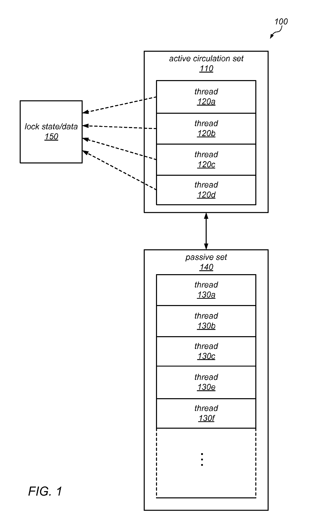
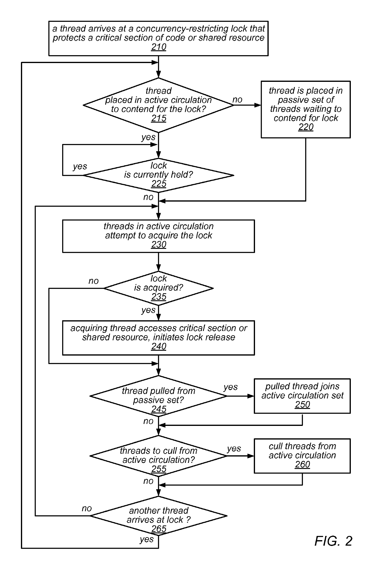
[0024]As noted above, as multicore applications mature, developers may face situations in which there are too many threads for the available hardware resources to be able to handle effectively and / or fairly. For example, this may been the case in component-based applications that employ thread pools. Often, such components have contended locks. In some embodiments of the systems described herein, concurrency-restricting modifications to those locks may be leveraged to restrict the number of threads in circulation, thus reducing destructive interference (e.g., in last-level shared caches, or for other types of shared resources).

[0025]For example, in some cases, a contended lock that protects and / or controls access to a critical section of code (CS) or shared resource may have an excessive number of threads circulating through the contended lock. In this context, the term “excessive” may refer to a situation in which there are more than enough threads circulating over the lock to keep...


PUM


Abstract

A concurrency-restricting lock may divide a set of threads waiting to acquire the lock into an active circulating set (ACS) that contends for the lock, and a passive set (PS) that awaits an opportunity to contend for the lock. The lock, which may include multiple constituent lock types, lists, or queues, may be unfair over the short term, but improve throughput of the underlying multithreaded application. Culling and long-term fairness policies may be applied to the lock to move excess threads from the ACS to the PS or promote threads from the PS to the ACS. These policies may constraint the size or distribution of threads in the ACS (which may be NUMA-aware). A waiting policy may avoid aggressive promotion from the PS to the ACS, and a short-term fairness policy may move a thread from the tail of a list or queue to its head.

Description

BACKGROUND[0001]Field of the Disclosure[0002]This disclosure relates generally to managing accesses to shared resources in a multithreaded environment, and more particularly to systems and methods for performing concurrency restriction and throttling over contended locks.[0003]Description of the Related Art[0004]In a multiprocessor environment with threads and preemptive scheduling, threads can participate in a mutual exclusion protocol through the use of lock or “mutex” constructs. A mutual exclusion lock can either be in a locked state or an unlocked state, and only one thread can hold or own the lock at any given time. The thread that owns the lock is permitted to enter a critical section of code protected by the lock or otherwise access a shared resource protected by the lock. If a second thread attempts to obtain ownership of a lock while the lock is held by a first thread, the second thread will not be permitted to proceed into the critical section of code (or access the share...

Claims


Application Information

Patent Timeline
Patent Type & Authority Patents(United States)
IPC IPC(8): G06F9/52
CPCG06F9/526
Inventor DICE, DAVID
Owner ORACLE INT CORP
Learn More