Method for producing water-atomized metal powder

a technology of metal powder and water atomization, which is applied in the direction of magnetic materials, magnetic bodies, electrical equipment, etc., can solve the problems of difficult contact between the surface of molten metal and the cooling water, preventing the promotion of cooling, and film boiling is likely to occur, etc., to achieve rapid cooling, simple method, and easy production

Active Publication Date: 2020-03-17
JFE STEEL CORP
View PDF35 Cites 0 Cited by
  • Summary
  • Abstract
  • Description
  • Claims
  • Application Information

AI Technical Summary

Benefits of technology

[0019]In order to quench high-temperature molten metal, cooling water is usually brought into contact with the molten metal. However, it is difficult for the surface of the molten metal to come into complete contact with the cooling water. This is because, at the moment when the cooling water comes into contact with the surface (surface to be cooled) of the high-temperature molten metal, the cooling water evaporates to form a vapor film between the cooled surface and the cooling water, resulting in a so-called film boiling state. Therefore, the presence of the vapor film prevents the promotion of cooling.

Problems solved by technology

However, it is difficult for the surface of the molten metal to come into complete contact with the cooling water.
Therefore, the presence of the vapor film prevents the promotion of cooling.
However, when the temperature of the divided metal particles is high, film boiling is likely to occur in the coolant layer and the metal particles supplied into the coolant layer move together with the coolant layer.
Therefore, the difference in relative speed between the coolant layer and each metal particle is small and there is a problem in that it is difficult to avoid film boiling.
In cooling in the film boiling region, a vapor film is present between a cooled surface and cooling water, resulting in weak cooling.
Therefore, in the case where cooling is started from the MHF point or higher for the purpose of amorphizing a metal powder, there is a problem in that the cooling rate for amorphization is too small and insufficient.
The gas atomization method requires a large amount of an inert gas for atomization and therefore has a problem that an increase in production cost is caused.

Method used


Image

  • Method for producing water-atomized metal powder
  • Method for producing water-atomized metal powder
  • Method for producing water-atomized metal powder

Examples


example 1

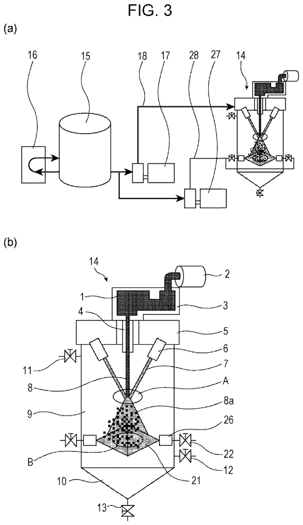
[0079]Each metal powder was produced using a water-atomized metal powder production apparatus shown in FIG. 3.

[0080]Raw materials were blended (partly containing impurities is inevitable) such that an Fe—B alloy (Fe83B17) with a composition of 83% Fe-17% B and an Fe—Si—B alloy (Fe79Si10B11) with a composition of 79% Fe-10% Si-11% B on an atomic basis were obtained, followed by melting the raw materials at about 1,550° C. in a melting furnace 2, whereby about 50 kgf of each molten metal was obtained. The obtained molten metal 1 was slowly cooled to 1,350° C. in the melting furnace 2 and was then poured into a tundish 3. An inert gas valve 11 was opened in advance such that a chamber 9 had a nitrogen gas atmosphere. Before the molten metal was poured into the tundish 3, cooling water was supplied to a nozzle header 5 from a cooling water tank 15 (a volume of 10 m3) by operating a high-pressure pump 17, whereby jet water (fluid) 7 was ejected from water ejection nozzles 6. Furthermore,...

example 2

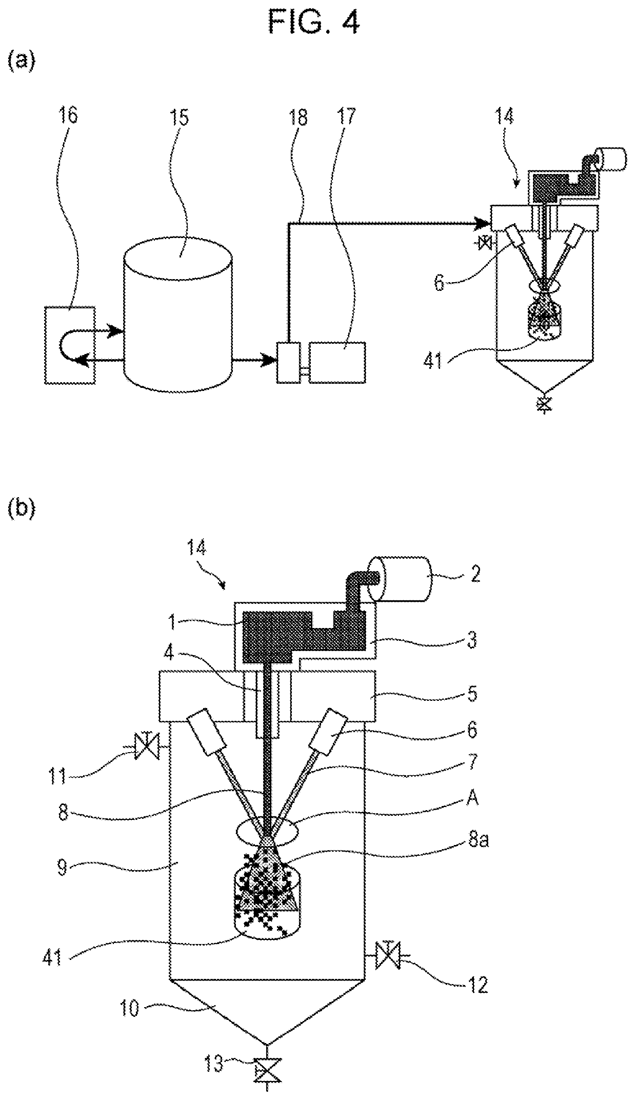
[0088]Each metal powder was produced using a water-atomized metal powder production apparatus shown in FIG. 4.

[0089]Raw materials were blended (partly containing impurities is inevitable) such that an Fe—B alloy (Fe83B17) with a composition of 83% Fe-17% B and an Fe—Si—B alloy (Fe79Si10B11) with a composition of 79% Fe-10% Si-11% B on an atomic basis were obtained, followed by melting the raw materials at about 1,550° C. in a melting furnace 2, whereby about 50 kgf of each molten metal was obtained. The obtained molten metal 1 was slowly cooled to 1,350° C. in the melting furnace 2 and was then poured into a tundish 3. An inert gas valve 11 was opened in advance such that a chamber 9 had a nitrogen gas atmosphere. Before the molten metal was poured into the tundish 3, cooling water was supplied to a nozzle header 5 from a cooling water tank 15 (a volume of 10 m3) by operating a high-pressure pump 17, whereby jet water (fluid) 7 was ejected from water ejection nozzles 6. A container ...

example 3

[0099]Each metal powder was produced using a water-atomized metal powder production apparatus shown in FIG. 5.

[0100]Raw materials were blended (partly containing impurities is inevitable) such that an Fe—B alloy (Fe83B17) with a composition of 83% Fe-17% B and an Fe—Si—B alloy (Fe79Si10B11) with a composition of 79% Fe-10% Si-11% B on an atomic basis were obtained, followed by melting the raw materials at about 1,550° C. in a melting furnace 2, whereby about 50 kgf of each molten metal was obtained. The obtained molten metal 1 was slowly cooled to 1,350° C. in the melting furnace 2 and was then poured into a tundish 3. An inert gas valve 11 was opened in advance such that a chamber 9 had a nitrogen gas atmosphere. Before the molten metal was poured into the tundish 3, cooling water was supplied to a nozzle header 5 from a cooling water tank (a volume of 10 m3) by operating a high-pressure pump, whereby jet water (fluid) 7 was ejected from water ejection nozzles 6. A collision plate ...


PUM

PropertyMeasurementUnit
ejection pressureaaaaaaaaaa
temperatureaaaaaaaaaa
flow velocityaaaaaaaaaa

Abstract

A method for producing a water-atomized metal powder, comprising applying water to a molten metal stream, dividing the molten metal stream into a metal powder, and cooling the metal powder, wherein the metal powder is further subjected to secondary cooling with cooling capacity having a minimum heat flux point (MHF point) higher than the surface temperature of the metal powder in addition to the cooling and the secondary cooling is performed from a temperature range where the temperature of the metal powder after the cooling is not lower than the cooling start temperature necessary for amorphization nor higher than the minimum heat flux point (MHF point).

Description

CROSS REFERENCE TO RELATED APPLICATIONS[0001]This is the National Phase Application of PCT / JP2016 / 001412, filed Mar. 14, 2016, which claims priority to JP 2015-068227, filed Mar. 30, 2015, the disclosures of these applications being incorporated herein by reference in their entireties for all purposes.TECHNICAL FIELD OF THE INVENTION[0002]The present invention relates to a method for producing a metal powder (hereinafter also referred to as a water-atomized metal powder) using a water atomizer and particularly relates to a method for increasing the cooling rate of a metal powder after water atomization.BACKGROUND OF THE INVENTION[0003]Conventional methods for producing a metal powder include atomization methods. The atomization methods include a water atomization method in which a metal powder is obtained by injecting a high-pressure water jet into a stream of molten metal and a gas atomization method in which an inert gas is ejected instead of a water jet.[0004]In the water atomiza...

Claims


Application Information

Patent Timeline
Patent Type & Authority Patents(United States)
IPC IPC(8): B22F9/08C22C45/02B22F9/00B22F9/02B22F1/00
CPCB22F9/02B22F9/08B22F9/002C22C45/02B22F9/082B22F2009/0872B22F2009/086B22F2009/0832B22F2009/0828C22C38/02B22F9/10H01F1/15308B22F9/008C22C38/002B22F2999/00
Inventor NAKASEKO, MAKOTOOZAKI, YUKIKONAKAMURA, NAOMICHI
Owner JFE STEEL CORP
Why Eureka
Try Eureka