Lighting fixture

a technology of led lighting and fixtures, applied in lighting and heating apparatus, lighting support devices, with built-in power, etc., can solve the problems of not offering a friendly way to do, not easy to have j-hooks reach the slots without several attempts, etc., and achieve the effect of easy approach

Active Publication Date: 2019-10-22
CHEN CHIA TEH
View PDF23 Cites 0 Cited by
  • Summary
  • Abstract
  • Description
  • Claims
  • Application Information

AI Technical Summary

Benefits of technology

[0017]In a certain embodiment, the recess has a wider end and taper toward to the recess slot end. Therefore, the clips of mounting plate can easily approach and being positioned to the wider end of the recess and further slid toward the recess slot.

Problems solved by technology

Because of slim thickness, probably less than 1 inch, it faces a challenge for designing a mounting system to easily install the flat panel light.
While the related art provides a way to install a thin flat panel light, however it does not offer a friendly way to do.
In particular, it is not easy to have J-hooks reaching the slots without several attempts.

Method used


Image

  • Lighting fixture
  • Lighting fixture
  • Lighting fixture

Examples


first embodiment

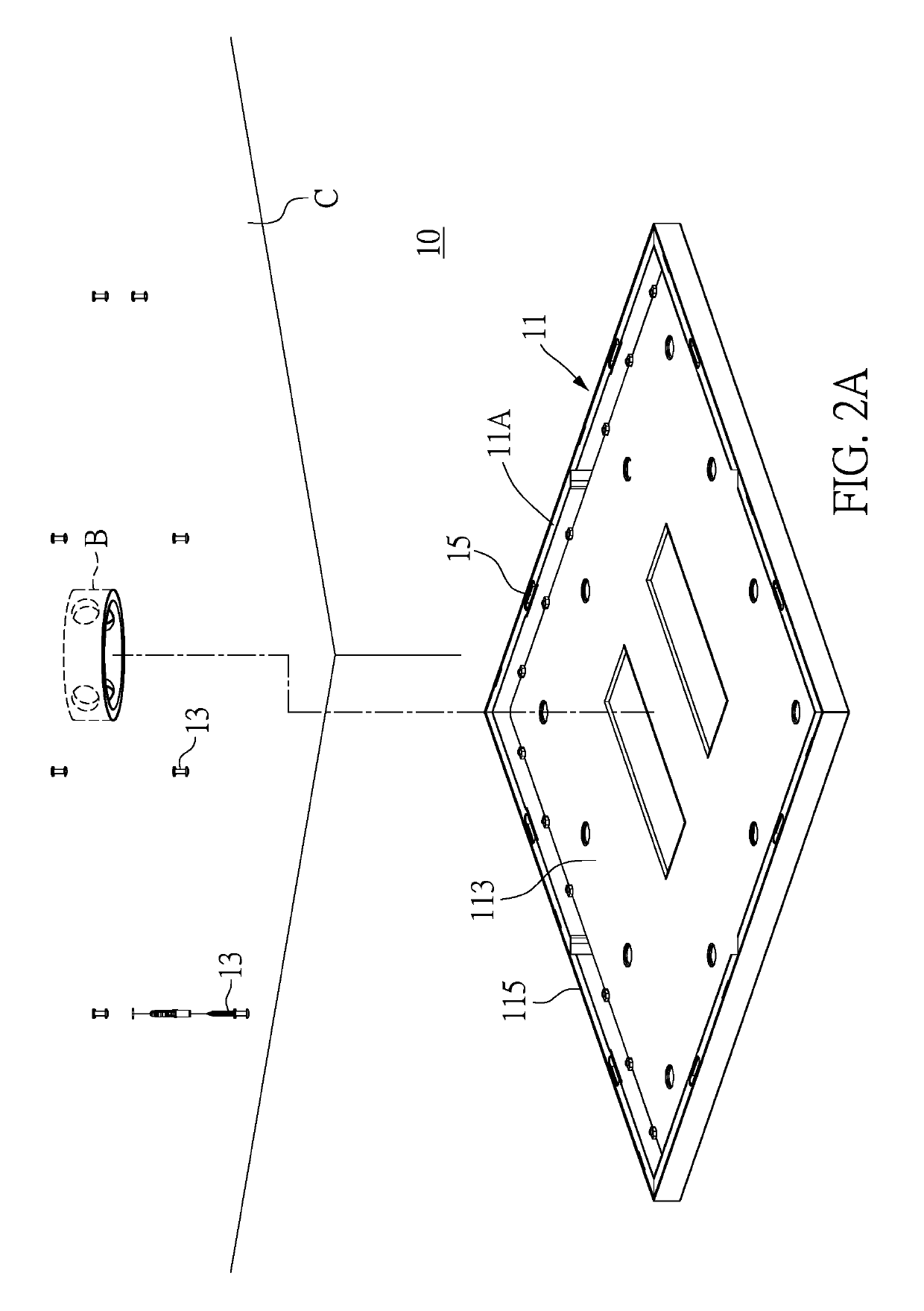
[0046]Reference is made to FIG. 2A and FIG. 2B. FIG. 2A illustrates schematically a simple exploded view of an LED panel lighting fixture 10 mounted onto a ceiling C according to the present disclosure. The LED lighting fixture 10 provides a set of mounting screws 13 pre-installed onto the ceiling C before a fixture body 11 is involved. The fixture body 11 includes a frame 11A, an LED light source assembly and a power supply. The frame 11A further includes an outer surrounding edge 115 and a back plate 113 to form an enclosed space to house the LED light source assembly and the power supply. The outer surrounding edge 115 includes at least two keyhole slots 15 allowing the fixture body 11 being mounted directly onto ceiling through engagement of the keyhole slots 15 and the mounting screws 13.

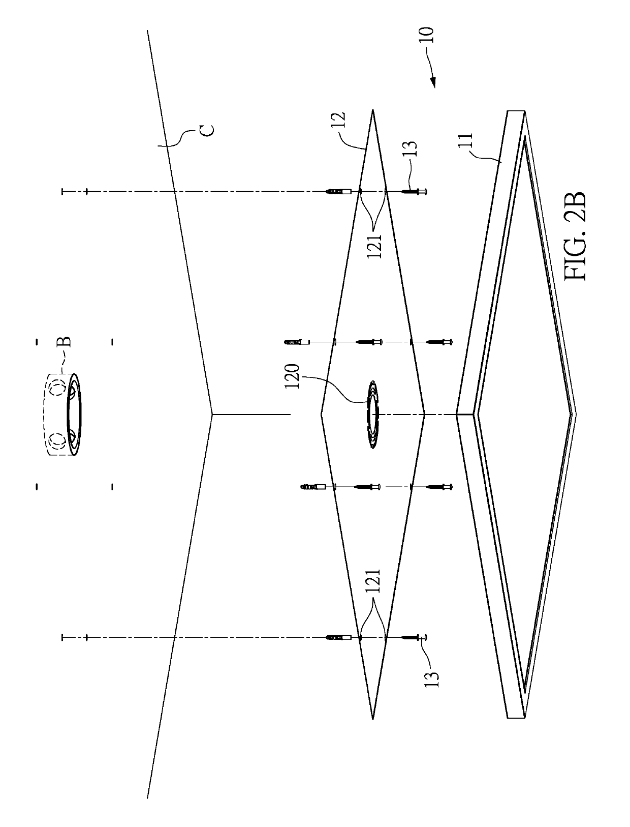
[0047]FIG. 2B illustrates schematically a guide plate 12 designed to assist the set of mounting screws to be installed onto ceiling at desired positions. The guide plate 12 is made of materials...

second embodiment

[0048]Reference is made to FIG. 3A to FIG. 3C, which schematically illustrate the present disclosure. Also referring to FIG. 2B, FIG. 3A to FIG. 3C disclose one way to engage a fixture body 21 onto the ceiling through pre-installed mounting screws 23 as described in FIG. 3A. The fixture body 21 has a number of keyhole slots 25 in correspondence to the mounting screws 23 and a top board 212 in FIG. 3B. The top board 212 has an elongated hole 210 with an identical width corresponding to the keyhole slot 25. The mounting screws 23 are step screws. Each step screw has a head portion 231 formed on a top end thereof, a thread portion 23A, a non-thread portion 23B, a stop portion 232 formed between the thread portion 23A and non-thread portion 23B. The step screw is pre-installed onto ceiling through the thread portion 23A only. The stop portion 232 is abutted against the ceiling. The non-thread portion 23B leaves a clearance that the fixture body 21 can be easily engaged with the mounting...

fourth embodiment

[0051]Reference is made to FIG. 6A, which illustrates schematically the present disclosure. A panel cover 57 is an outer surrounding frame having similar and slightly larger form of the outer surrounding edge 515. The panel cover 57 is configured to detachably engage with the fixture body 51 at the outer surrounding edge 515. The panel cover 57 can fully cover the outer surrounding edge 515 and serves as decorative cover of the fixture body 51. Because the panel cover 57 is detachably engaged with the fixture body 51, it can be separated from the fixture body 51 without using any tools but hands. The panel cover 57 can be additionally configured with a decorative motif 57A on an inside. Therefore, the LED panel lighting fixture 50 illuminating light is decorated with beautiful motifs thereon. The motif can be a geometric art, a life art or any décor art, which is an element of an image. A motif may be repeated in a pattern or design, often many times, or may just occur once in a wor...


PUM


Abstract

A slim lighting fixture is disclosed. Keyhole slots are provided along outer surrounding edge of the lighting fixture. A disposable guide plate is employed to mark locations of screws corresponding to the keyhole slots. Step-screws are installed on the locations marked. The lighting fixture is engaged with step-screws at the keyhole slots through recess, slide and lock. Alternatively, an engagement may be accomplished by screws inserted through the keyhole slots, slid and tightened. A decorative cover is designed to fit the lighting fixture at the outer surrounding edge. An indirect mounting system is provided. A lighting fixture has a recess and side slot at each of four quadrants of a back plate. A mounting plate has four clips corresponding positions of the recess. The lighting fixture is engaged with the mounting plate at the clips and recess / side slot through recess, slide and lock.

Description

CROSS-REFERENCE TO RELATED PATENT APPLICATION[0001]Some references, which may include patents, patent applications and various publications, may be cited and discussed in the description of this disclosure. The citation and / or discussion of such references is provided merely to clarify the description of the present disclosure and is not an admission that any such reference is “prior art” to the disclosure described herein. All references cited and discussed in this specification are incorporated herein by reference in their entireties and to the same extent as if each reference was individually incorporated by reference.FIELD OF THE DISCLOSURE[0002]The present invention relates to a LED lighting fixture and its mounting system. More specifically, the present invention utilizes various surface mounted skills to directly or indirectly mount a slim LED lighting fixture onto a surface of a ceiling or a wall. In addition, these skills also provide friendly installation, safety, operatin...

Claims


Application Information

Patent Timeline
Patent Type & Authority Patents(United States)
IPC IPC(8): F21V23/02F21S9/02F21V21/34F21V21/30F21V23/06F21Y115/10
CPCF21V23/06F21V21/30F21V23/023F21S9/02F21V21/34F21V2200/20F21Y2115/10F21V17/104F21V17/105F21V17/12F21V19/001F21V21/02F21V23/02F21K9/20F21S8/04F21Y2105/16
Inventor CHEN, CHIA-TEH
Owner CHEN CHIA TEH
Why Eureka
Try Eureka