Manipulator

Inactive Publication Date: 2020-03-26
KYUSHU UNIV
View PDF0 Cites 0 Cited by
  • Summary
  • Abstract
  • Description
  • Claims
  • Application Information

AI Technical Summary

Benefits of technology

The patent aims to reduce costs and improve efficiency by eliminating the need for a wire and using a small number of components. This makes it easier to reach the target lesion.

Problems solved by technology

Since the forceps used for minimally invasive surgery is restricted in postures thereof by incision holes in the body of the patient, the forceps can only approach from a limited direction to a target lesion.

Method used


Image

  • Manipulator
  • Manipulator
  • Manipulator

Examples


Embodiment Construction

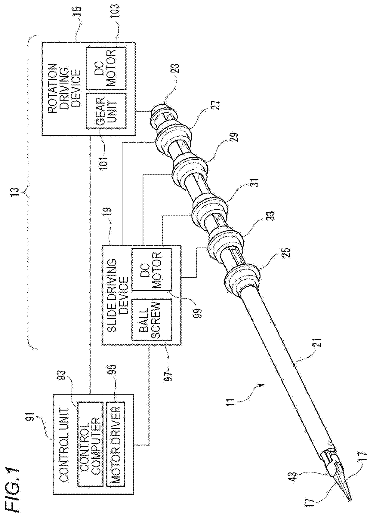
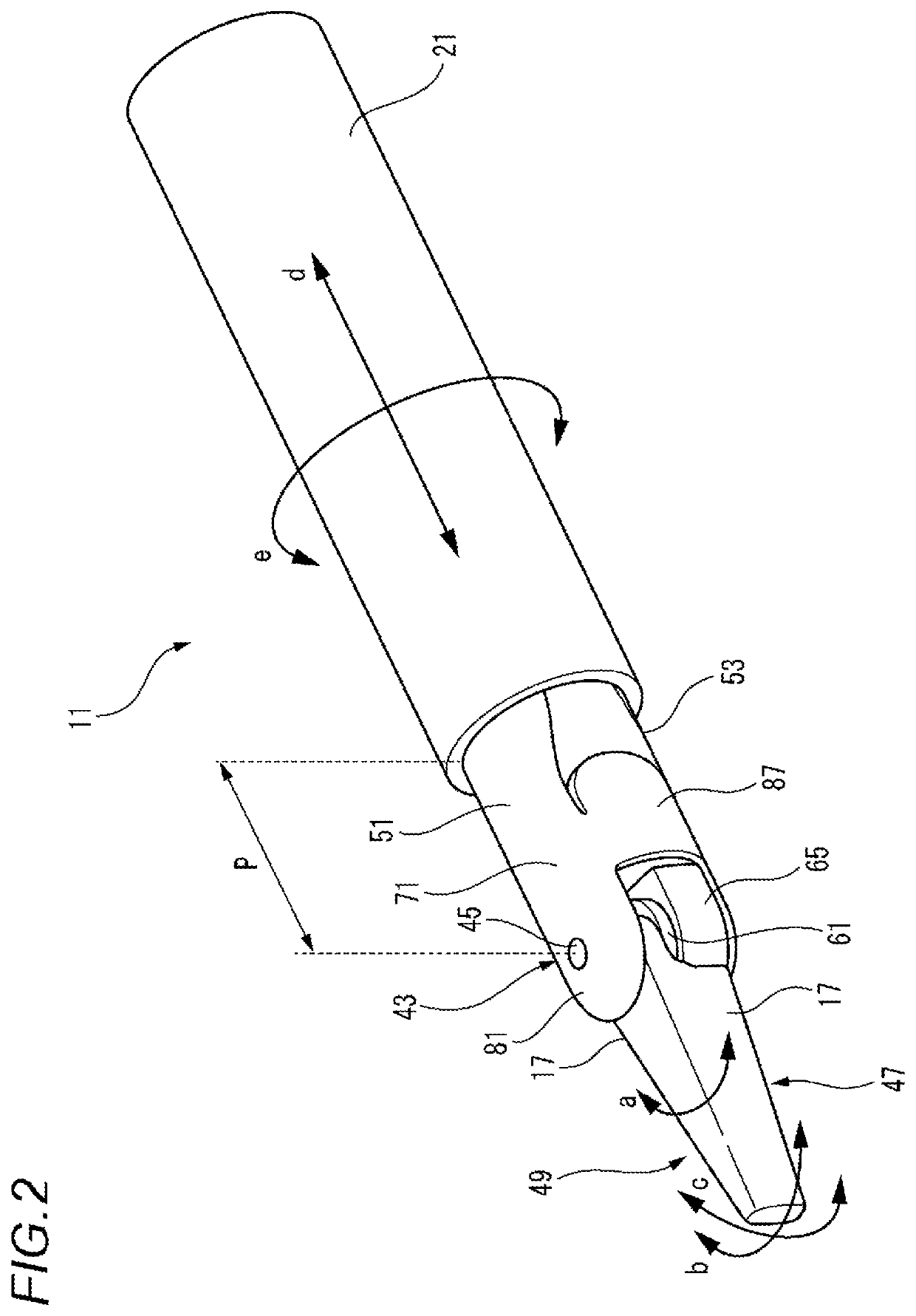
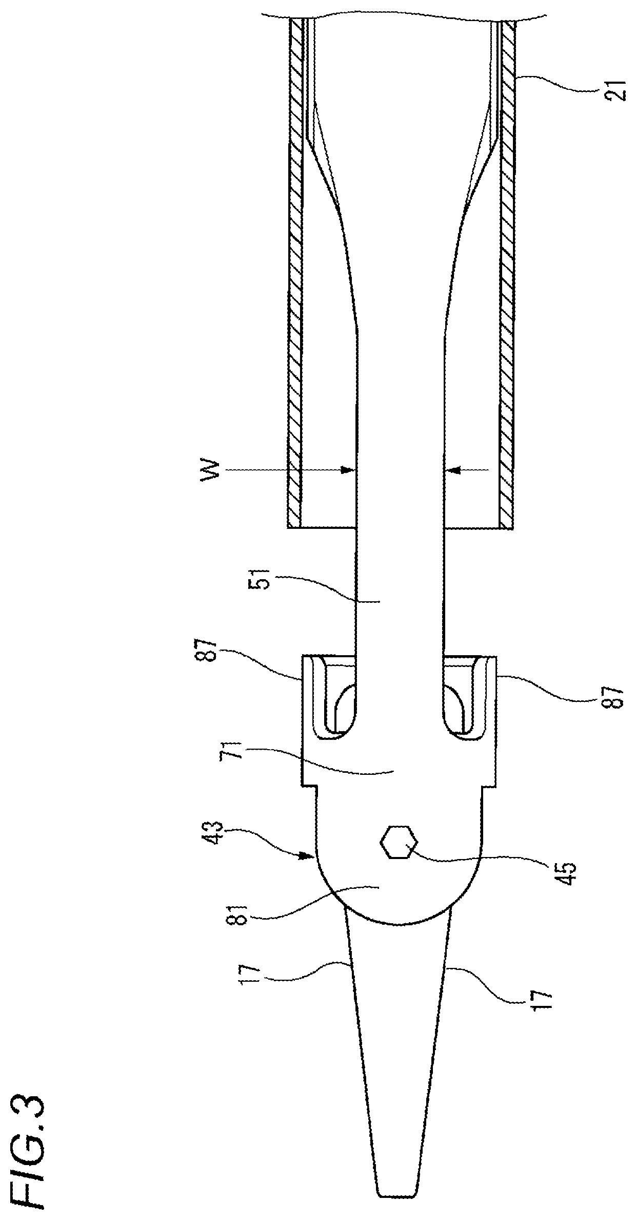
[0057]Hereinafter, an embodiment in which a manipulator according to the present disclosure (hereinafter referred to as the embodiment) specifically disclosed will be described in detail with reference to the drawings as appropriate. Detailed description more than necessary may be omitted in some cases. For example, detailed descriptions of already well-known matters and redundant descriptions on substantially the same configuration may be omitted in some cases. This is to avoid the unnecessary redundancy of the following description and to make it easy to understand for those skilled in the art. In addition, the attached drawings and the following description are provided to enable those skilled in the art to fully understand the present disclosure, and are not intended to limit the subject matter described in the claims. In addition, in the following embodiment, the manipulator according to the present disclosure will be described by exemplifying a manipulator used for laparoscopi...


PUM


Abstract

A manipulator includes a pair of flexible operating bodies including a horizontal plate spring, a curved vertical plate spring, a shaft body, and an operation portion. The pair of flexible operating bodies overlaps such that a second flexible operating body on one side is opposite to a first flexible operating body on the other side, and is linked to each other to be rotatable by a pin penetrating respective shaft bodies. In a holder that supports both ends of the pin, a pair of outer horizontal plate springs that has the horizontal plate springs of each of the pair of flexible operating bodies to be interposed in parallel between the holder and extends in the same direction as the horizontal plate spring is integrally formed.

Description

TECHNICAL FIELD[0001]The present disclosure relates to a manipulator.BACKGROUND ART[0002]In recent years, minimally invasive surgery represented, for example, by laparoscopic surgery attracts attention as one method of a surgical operation. In the minimally invasive surgery, surgical instruments such as an endoscope or a forceps are inserted into a body through a small incision hole of approximately 5 mm to 10 mm opened in a body surface, and surgery is performed inside the body. Therefore, compared to ordinary surgical operations (for example, open chest surgery or open abdominal surgery), there is an advantage that damage to the body of a patient at the time of surgery and pain after surgery can be minimized.[0003]Since the forceps used for minimally invasive surgery is restricted in postures thereof by incision holes in the body of the patient, the forceps can only approach from a limited direction to a target lesion. In order to easily perform work, such as griping and ligating,...

Claims


Application Information

Patent Timeline
IPC IPC(8): A61B17/29B25J17/00
CPCA61B2017/00836A61B17/29A61B17/295A61B2017/00867B25J17/00A61B2017/00526A61B2017/00862A61B2017/2927A61B2017/2937A61B2017/2939A61B17/28
Inventor ARATA, JUMPEIHASHIZUME, MAKOTO
Owner KYUSHU UNIV
Why Eureka
Try Eureka