
Thermoelectric vehicle system

a technology of electric vehicles and vehicles, applied in vehicle sub-unit features, greenhouse gas reduction, nuclear reactors, etc., can solve the problems of repeated recharging, severe limitations in the range of electric vehicles, and the current production of sustainable electric vehicles suffer from a number of shortcomings, so as to achieve sustainable and cost-effective effects

Active Publication Date: 2019-11-12
LENR CARS SA
View PDF85 Cites 2 Cited by
  • Summary
  • Abstract
  • Description
  • Claims
  • Application Information

AI Technical Summary

Benefits of technology

The invention is a system that uses heat generated by a reaction of nickel powder and hydrogen to produce electricity. This electricity is then stored in a battery. The system also includes a cooling system to keep the components cool and a control system to manage the overall operation. The technical effect of this invention is to provide an efficient, sustainable, and cost-effective way to power vehicles.

Problems solved by technology

However, even these sustainable electric vehicles currently being produced suffer from a number of shortcomings.
When such batteries are utilized as the sole source of power, the range of the electric vehicle is severely limited by the storage capacity of the batteries and thus require repeated recharging.
However, such systems often must rely on a complex hydrogen infrastructure and a network of hydrogen stations to provide points of delivery of hydrogen to refill the vehicles (much like gas stations).
The necessary hydrogen infrastructure to support widely-used fuel cell vehicles is estimated to take several decades.
Nonetheless, all of these solutions suffer many drawbacks compared to standard thermal engine vehicles, including range, usability, comfort and cost.

Method used


Image

  • Thermoelectric vehicle system
  • Thermoelectric vehicle system
  • Thermoelectric vehicle system

Examples


Embodiment Construction

A. Overview.

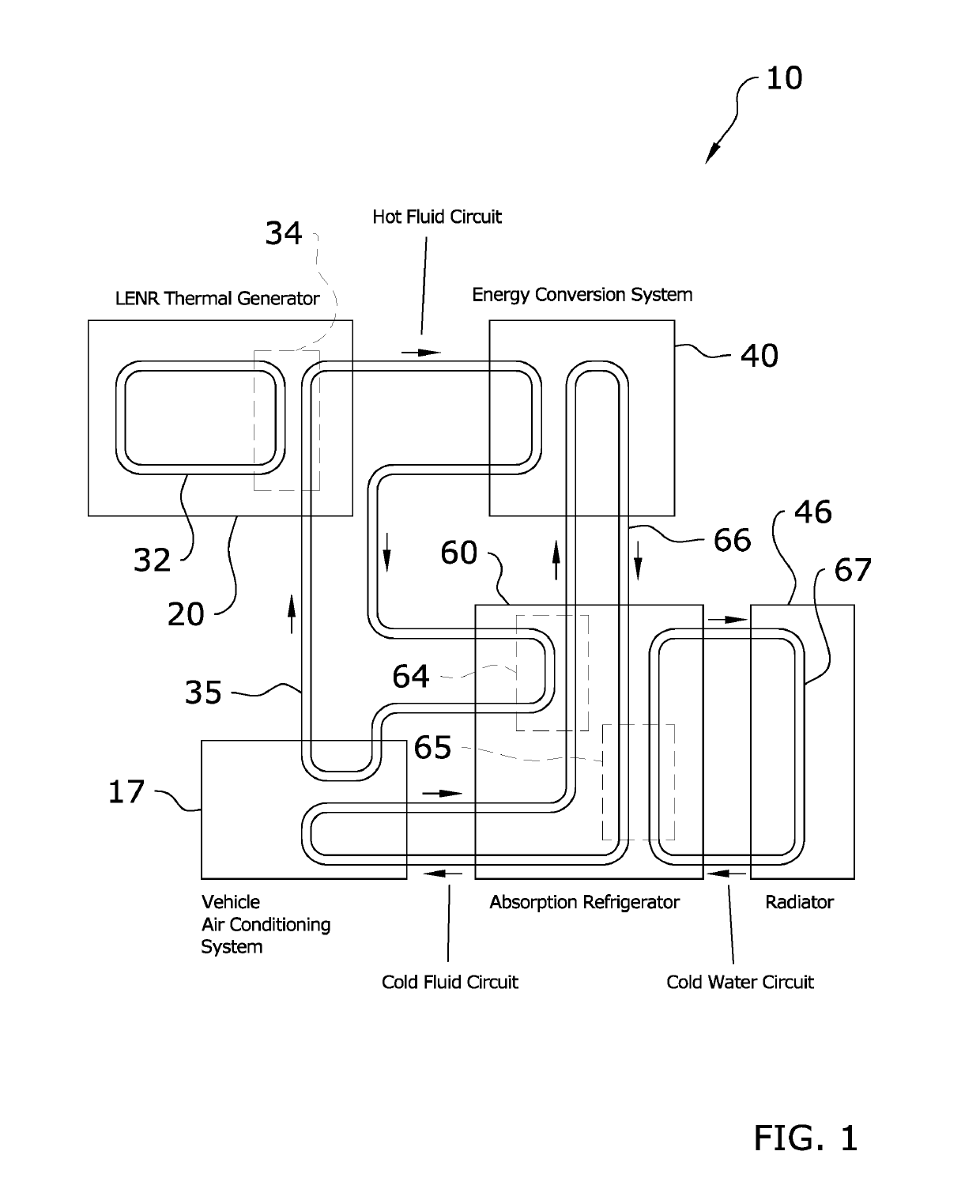
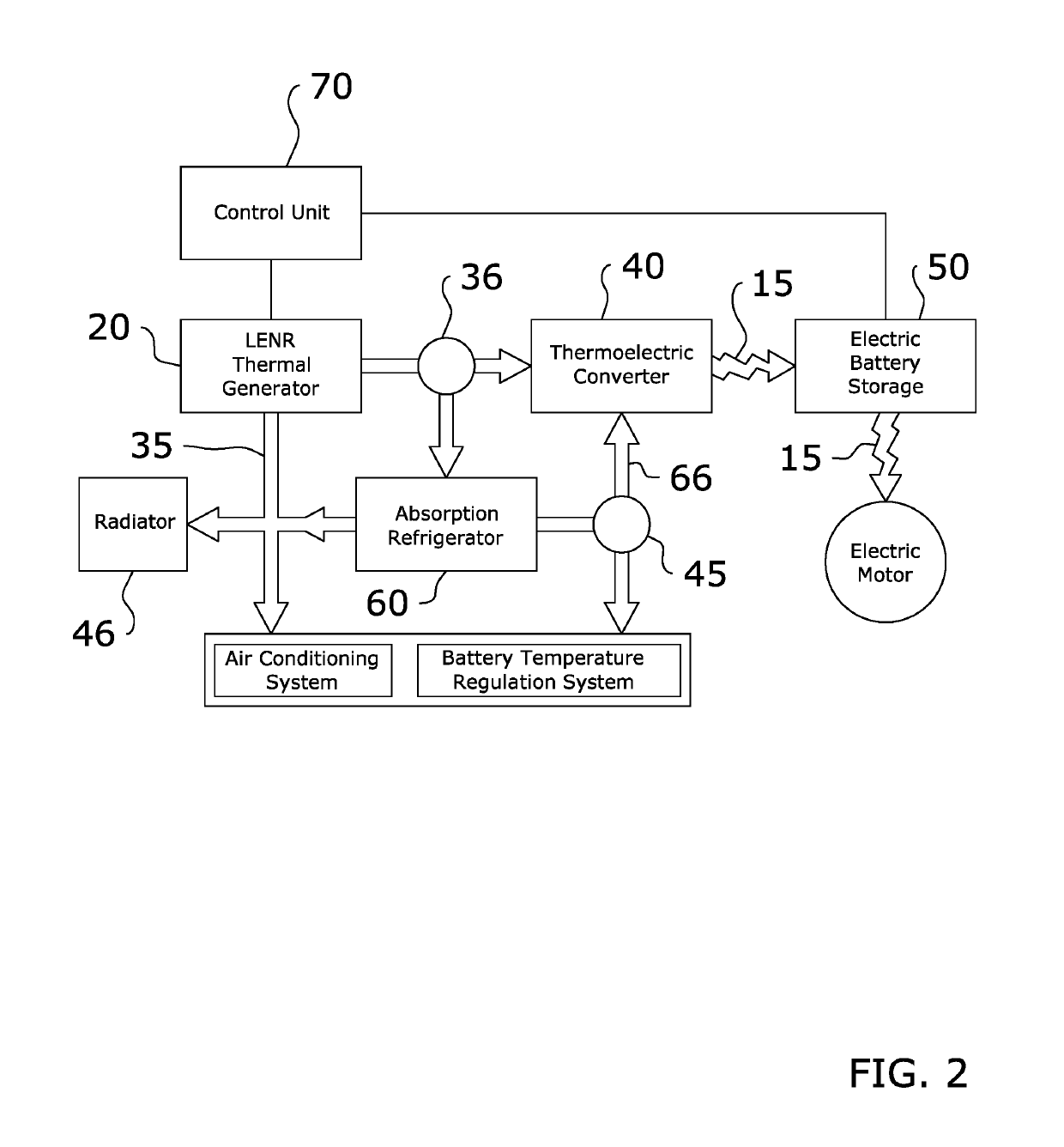
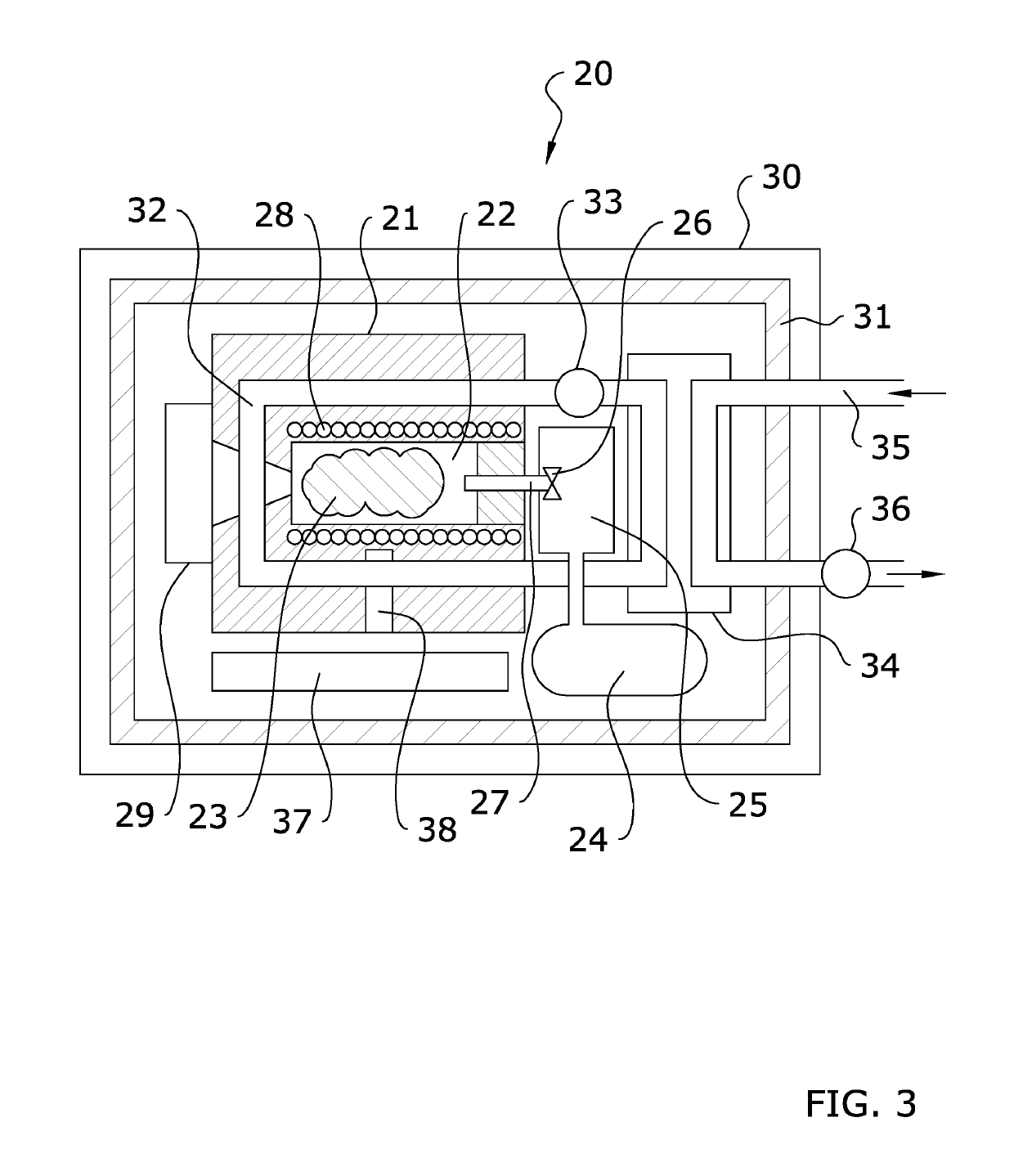
[0023]Turning now descriptively to the drawings, in which similar reference characters denote similar elements throughout the several views, FIGS. 1 through 7 illustrate a thermoelectric vehicle system 10, which comprises a thermal generator 20 within a thermal enclosure case 30, an energy conversion system 40 linked with the thermal generator 20, an energy storage system 50 linked with the energy conversion system 40, a cooling system 60 and a central control system 70. The thermal generator 20 reacts nickel powder 23 with hydrogen within a reactor chamber 22 to produce heat. The heat is then transferred to the energy conversion system 40 to be converted into electricity for storage in the energy storage system 50 such as a battery. The cooling system 60 provides cooling for the various components of the present invention and the control system 70 regulates its overall operation.

[0024]FIGS. 1 and 2 show block diagrams illustrating the overall structure and operation of ...


PUM


Abstract

A thermoelectric vehicle system which provides a cost-effective and sustainable means of transportation for long operation range with zero emission using an onboard low energy nuclear reaction thermal generator. The present invention generally includes a thermal generator within a thermal enclosure case, an energy conversion system linked with the thermal generator, an energy storage system linked with the energy conversion system, a cooling system and a central control system. The thermal generator reacts nickel powder with hydrogen within a reactor chamber to produce heat. The heat is then transferred to the energy conversion system to be converted into electricity for storage in the energy storage system. The cooling system provides cooling for the various components of the present invention and the control system regulates its overall operation. The present invention may be utilized to power a vehicle in an efficient, sustainable and cost-effective manner.

Description

CROSS REFERENCE TO RELATED APPLICATIONS[0001]The present application is a continuation-in-part of U.S. application Ser. No. 13 / 848,888 filed on Mar. 22, 2013, which claims priority to U.S. Provisional Application No. 61 / 617,135 filed Mar. 29, 2012. Each of the aforementioned patent applications, and any applications related thereto, is herein incorporated by reference in their entirety.STATEMENT REGARDING FEDERALLY SPONSORED RESEARCH OR DEVELOPMENT[0002]Not applicable to this application.BACKGROUND OF THE INVENTIONField of the Invention[0003]The present invention relates generally to a thermoelectric vehicle system and more specifically it relates to a low energy nuclear reaction thermoelectric vehicle system which provides a cost-effective and sustainable means of transportation for long operation range with zero emission using an onboard low energy nuclear reaction thermal generator.Description of the Related Art[0004]Any discussion of the related art throughout the specification ...

Claims


Application Information

Patent Timeline
Patent Type & Authority Patents(United States)
IPC IPC(8): H01L35/30H10N10/13
CPCH01L35/30B60Y2400/206G21B3/00G21D5/02B60L50/50B60L50/15B60L58/26B60L58/27Y02E30/10Y02T10/70Y02T10/7072Y02E30/00H10N10/13
Inventor CHAUVIN, NICOLAS
Owner LENR CARS SA
Learn More