Method and equipment for production of a pinch line free liner

a production method and technology of a pinch line, applied in the field of pinch line free liner production, can solve the problems of unsatisfactory, uneven outer surface of the moulded object, and the reliability of the container, and achieve the effect of reducing or eliminating the presence of one or more pinch lines

Active Publication Date: 2019-11-26
HEXAGON TECH H2 AS
View PDF19 Cites 0 Cited by
  • Summary
  • Abstract
  • Description
  • Claims
  • Application Information

AI Technical Summary

Benefits of technology

[0008]The objective of the present invention is to provide an alternative method for blow moulding a liner reducing or eliminating the presence of one or more pinch lines.
[0009]A further objective is to provide a method and system that eliminates the pinch line at both ends of a cylindrical liner.
[0011]A further objective is to provide a method and device which eliminates or limits the need for additional steps to obtain a liner ready for installation of a boss.
[0018]The feature that the circumference of the at least one aperture is larger than or equal to a circumference of the parison provides for arrangement of the parison within the aperture such that pinching of the section of the parison arranged within the aperture is avoided. The moulding equipment can be closed before the parison is arranged therein or the equipment can be closed around the parison either way the larger diameter of the circumference of the aperture provides for the pinch-free arrangement of the parison within the moulding equipment.
[0041]In yet another aspect of the blow moulding equipment according to the present invention the moulding cavity and the at least one aperture are arranged reversible movable away from and towards each other in the axial direction, where the axial direction should be understood in relation to central axis through the aperture. This movement provides for cutting and thereby separation of a blow moulded element prepared in the moulding cavity from the scrap in the aperture and optional outside the aperture by the cutting edge. In an additional aspect of the blow moulding equipment the at least one aperture comprises grabbing tools for grabbing a blow moulded element when the moulding cavity and the at least one aperture are moved away from each other. The grabbing tool holds the scrap section arranged in the aperture and allows for this section to be pulled away from the container prepared in the moulding cavity.
[0046]The container prepared by the method of the present application can be utilized as a liner for a composite pressure container. The composite pressure container may for instance be used for storing and transporting LPG (liquefied petroleum gas), CNG (compressed natural gas), or hydrogen. By providing a method of producing a pinch line free liner the process of attaching the boss to the liner for composite pressure containers is improved and possibly simplified.

Problems solved by technology

This uneven thickness may influence the reliability of the container to store fluid under pressure.
Further the pinch line in the area surrounding the opening makes the outer surface of the moulded object uneven and non-smooth often with dents at the ends of the pinch line.

Method used


Image

  • Method and equipment for production of a pinch line free liner
  • Method and equipment for production of a pinch line free liner
  • Method and equipment for production of a pinch line free liner

Examples


Embodiment Construction

[0061]The present invention is explained in further detail with reference to the enclosed figures illustrating an embodiment of the invention. The same reference signs are used to refer to the same elements illustrated in different drawings.

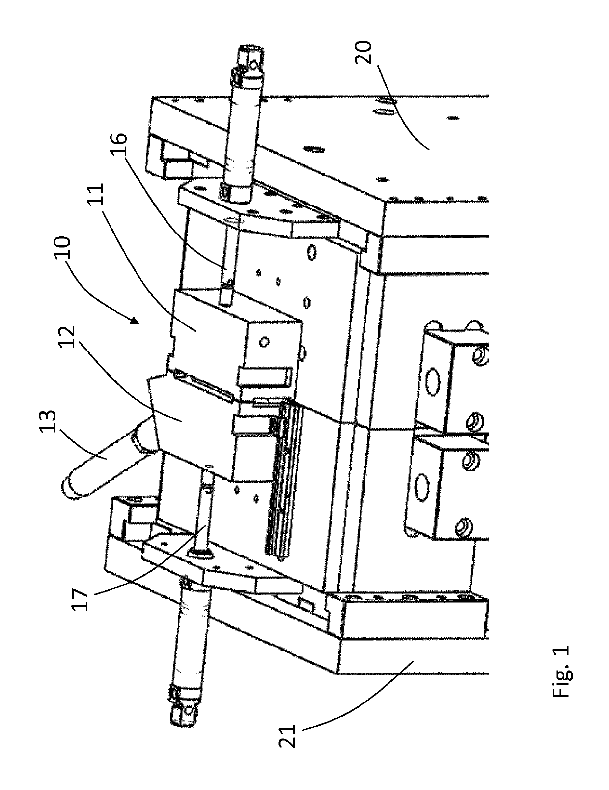
[0062]FIG. 1 illustrates a perspective view of a top section of moulding equipment for preforming the method according to the present invention. Two mould parts 20 and 21 form a moulding cavity, not visible in this illustration. The moulding cavity defines the form of the blow moulded liner. An opening for arrangement of a parison within the moulding cavity is arranged between the two mould parts 20 and 21 at the top of the moulding cavity. The opening is covered by a shutter system 10 comprising a first shutter element 11 and a second shutter element 12. The first and second shutter elements 11 and 12 are arranged to be movable towards each other to a closed position as illustrated on FIG. 1 and to be movable away from each other to an open posi...


PUM

PropertyMeasurementUnit
circumferenceaaaaaaaaaa
volumeaaaaaaaaaa
pressureaaaaaaaaaa

Abstract

Method of blow moulding a container from a hollow, elongated parison of a thermoplastic material, wherein the method comprises: —arranging the parison in a closed moulding equipment comprising a moulding cavity and at least one aperture, wherein the at least one aperture provides an opening into the moulding cavity from outside the closed moulding equipment, wherein the circumference of the at least one aperture is larger than or equal to a circumference of the parison, such that a first section of the parison is arranged inside the moulding cavity, a second section of the parison is arranged within the at least one aperture and a third section of the parison is arranged outside the closed moulding equipment, —closing a shutter system around the third section of the parison, thereby pinching the parison and providing a closed volume inside the first and second sections of the parison, —arranging a blow conduit in fluid communication with the closed volume inside the second section of the parison, —blowing pressurised gas from the blow conduit into the first and the second section of the parison, thereby forming first and second blow moulded sections, wherein the first blow moulded section is the container, and—separating the second blow moulded section from the first blow moulded section, thereby providing an opening in the container.

Description

[0001]The present invention relates to a method of blow molding a container as well as equipment adapted to perform the method. More specifically the present invention relates to a method for producing a pinch line free liner for a composite pressure container and equipment for performing the method.BACKGROUND[0002]A common type of composite pressure containers consist of an internal fluid tight liner, at least one boss connected thereto for installation of a valve, safety device, or similar connection devices for filling or emptying of the container. On the outside of the liner one or more reinforcement layers are arranged to provide the container with the necessary strength to store fluid under a desired pressure. These types of containers are for instance disclosed in WO00 / 66939 and WO98 / 34063 where the reinforcement layer comprises resin coated fibres.PRIOR ART[0003]The liner for the pressure containers have traditionally been produced by blow moulding. The process of convention...

Claims


Application Information

Patent Timeline
Patent Type & Authority Patents(United States)
IPC IPC(8): B29C49/42B29C49/04B29C49/48B29C49/50B29C49/60B29C49/44B29K101/12B29K105/00B29L31/00
CPCB29C49/04B29C49/50B29C49/4273B29C49/4278B29C49/60B29C49/42B29C2049/6072B29K2105/258B29K2101/12B29C49/44B29L2031/7158B29C49/4205B29C49/22B29C49/28
Inventor GÅRDSRUD, HANS ØYVINDTHÉVENARD, PIERRE
Owner HEXAGON TECH H2 AS
Why Eureka
Try Eureka