
Method for the production of a dressing tool for a grinding tool

a technology of grinding tool and production method, which is applied in the direction of grinding machine components, grinding machine components, abrasive surface conditioning devices, etc., can solve the problems of very laborious production process and profile defects, and achieve the effect of eliminating profile defects of dressing tool and precise geometry

Active Publication Date: 2019-12-17
KAPP WERKZEUGMASCH +1
View PDF17 Cites 0 Cited by
  • Summary
  • Abstract
  • Description
  • Claims
  • Application Information

AI Technical Summary

Benefits of technology

[0009]Thus, it is an object of the invention to design a generic method in such a manner that the profile of the produced dressing tool corresponds as good as possible to the ideal contour; so, profile defects of the dressing tool should be eliminated. Especially it should be made sure that the deformation of the nickel layer remains as small as possible. Accordingly the dressing tool should have a precise geometry as much as possible.

Problems solved by technology

The production process is thereby very laborious.
Furthermore, also thermal tensions are noticed which lead to defects in the profile.

Method used


Image

  • Method for the production of a dressing tool for a grinding tool
  • Method for the production of a dressing tool for a grinding tool
  • Method for the production of a dressing tool for a grinding tool

Examples


Embodiment Construction

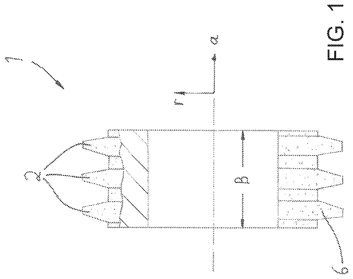
[0035]In FIG. 1 a dressing tool 1 being a dressing roll is shown. The dressing tool 1 consists of a rotationally symmetric part which comprises a direction of the axis a as well as a radial direction r. The dressing tool 1 has a width B in axial direction.

[0036]In the embodiment the dressing tool 1 has three ring-shaped projections 2 which run in circumferential direction and which extend in radial direction r. Those projections 2 are provided with abrasive material 6 in the form of diamond powder (with corresponding grain size; dependent from the grinding tool to be dressed) so that with the dressing tool 1 a grinding worm can be dressed. This process is known as such and needs not to be explained here in detail.

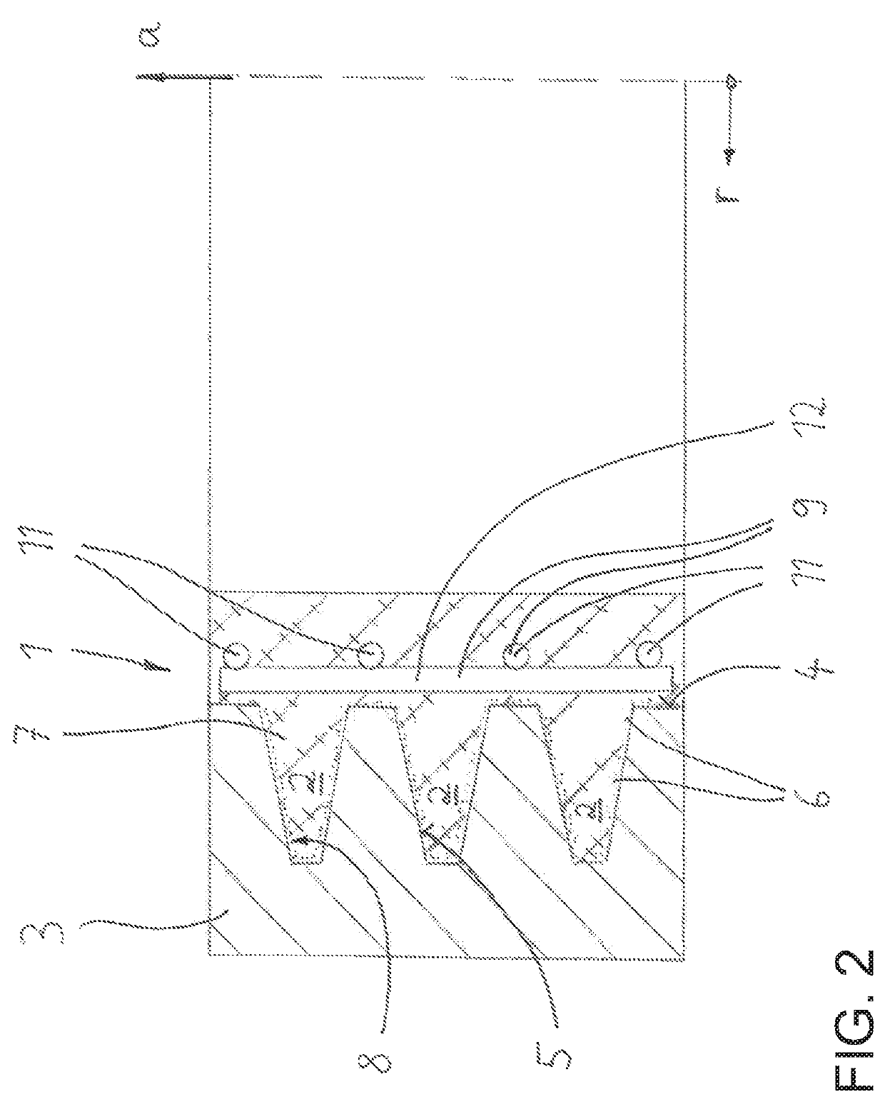
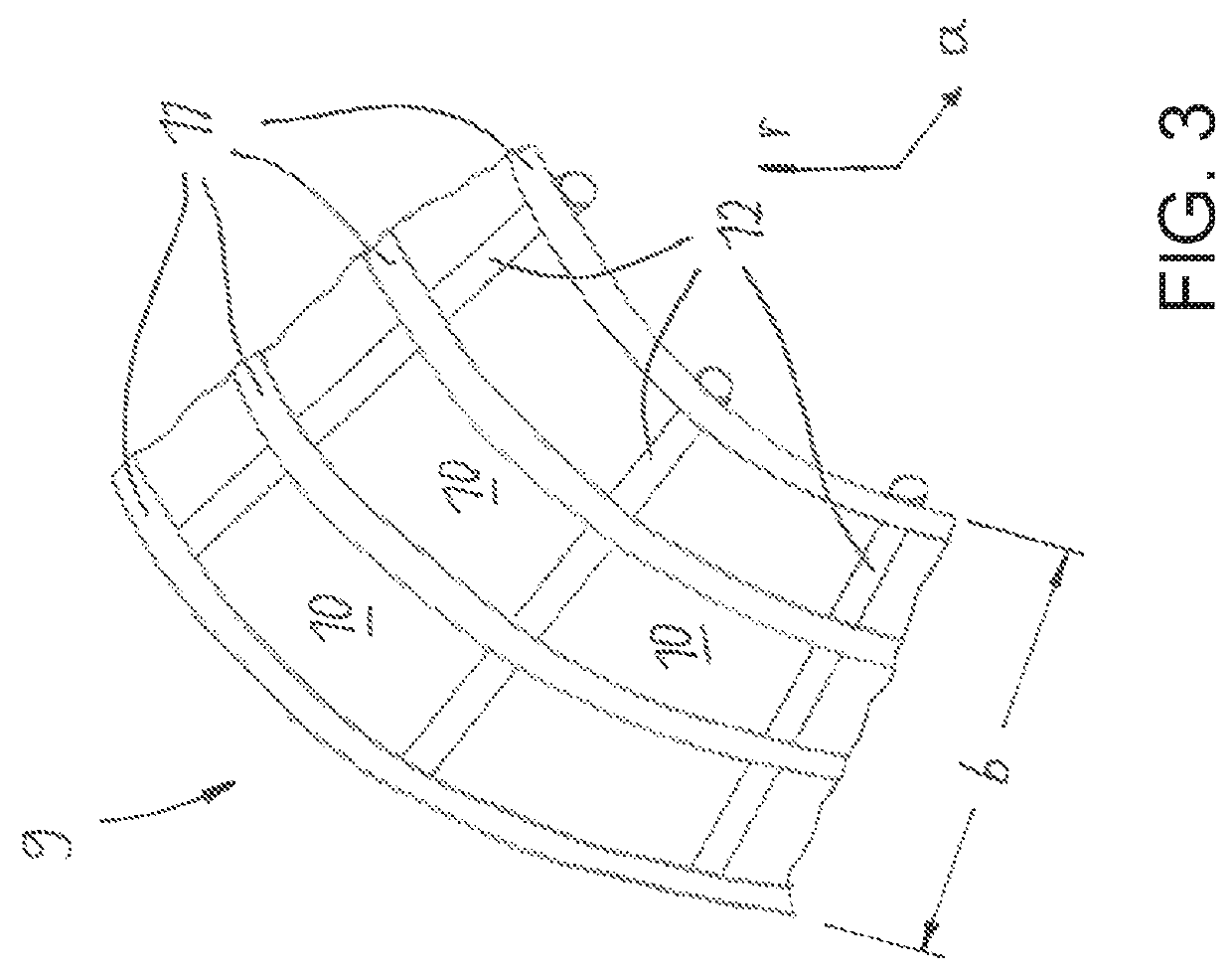
[0037]The production of such a dressing tool 1 is depicted in FIG. 2. Central element for the production is a shaped ring 3 which has a substantial hollow-cylindrical shape. At a radial inner area 4 of the shaped ring 3 recesses 5 are machined (i. e. ground with high precis...


PUM


Abstract

A method for the dressing of a multi-thread grinding worm by a dressing roll, wherein the grinding worm has at least two screw channels which are arranged parallel to another, which screw channels extend helically around an axis of the grinding worm and wherein the dressing roll has at least two adjacent dressing profiles which are arranged along an axis of the dressing roll, wherein the dressing profiles of the dressing roll are guided simultaneously through adjacent screw channels of the grinding worm during the dressing of the grinding worm. To improve the precision of the dressing the method includes the steps: a) execution of a first partial dressing process at which the dressing profiles of the dressing roll are guided simultaneously through first adjacent screw channels of the grinding worm; b) execution of at least one second partial dressing process at which the dressing profiles of the dressing roll are guided simultaneously through second adjacent screw channels of the grinding worm, wherein the second adjacent screw channels are, compared with step a), offset in the direction of the axis of the grinding worm by at least one screw channel of the grinding worm.

Description

CROSS-REFERENCE TO RELATED APPLICATIONS[0001]The present application claims priority of DE 10 2016 006 951.1, filed Jun. 8, 2016, the priority of this application is hereby claimed and this application is incorporated herein by reference.BACKGROUND OF THE INVENTION[0002]The invention relates to a method for the production of a dressing tool for a grinding tool, preferably for a grinding worm, wherein the dressing tool comprises at least one, preferably ring-shaped designed projection which extends radially.[0003]At the machining especially of gearings with generative tools normally a dressable multi-thread grinding worm is used. The dressing of the grinding worm takes place in turn with a single- or multi-groove dressing roll. The present invention relates a method for the production of such a dressing tool. Preferably, thereby multi-groove full profile rolls are provided which can be used for an efficient dressing of grinding worms.[0004]A method of the generic kind is described in...

Claims


Application Information

Patent Timeline
Patent Type & Authority Patents(United States)
IPC IPC(8): B24B53/075B24B53/085B24B53/14B24D18/00
CPCB24B53/14B24B53/075B24B53/085B24D18/00B24D18/0018
Inventor SCHMUECK, FRIEDRICH
Owner KAPP WERKZEUGMASCH
Learn More