
Technology for manufacturing steel plastic composite section bar

A composite profile and manufacturing process technology, applied in the direction of the wing frame and other directions, can solve the problems of stress deformation of composite profiles, reduce the strength of composite profiles, and low plastic strength, and achieve the effects of precise geometric dimensions, guaranteed stability and clear lines.

Active Publication Date: 2011-05-18
重庆华厦门窗有限责任公司
View PDF2 Cites 0 Cited by
  • Summary
  • Abstract
  • Description
  • Claims
  • Application Information

AI Technical Summary

Problems solved by technology

Due to the small elastic modulus of plastic, it will be deformed or damaged when subjected to high pressure, thus affecting product quality
[0006] 2. Due to the small elastic modulus of the plastic, it cannot effectively resist the pressure of the roll when the steel profile is deformed, so that the internal stress of the steel profile cannot be effectively released. When the pressure of the roll disappears, the steel profile will rebound , the steel profile and the plastic profile cannot be tightly combined, and the overall stress deformation of the composite profile will be caused, which will further affect the product quality
[0007] 3. Due to the low strength of plastic, when the steel profile is deformed and compressed, the pressure will cause the plastic profile under the steel profile to be compressed, especially the compression of the top corner of the plastic profile will enlarge the R angle at the corner of the steel profile , affecting the appearance quality of steel profiles;
[0008] 4. There is a big gap between the temperature deformation properties of steel profiles and plastic profiles. In this method, the plastic profiles based on the screw extruder are directly transported to the composite rolling mill for compounding. Since the necessary plastic shrinkage deformation period has not passed, the composite profiles will be due to plastic deformation. Shrinkage does not match the length of the steel profile, and defects such as twisting and side bending of the composite profile
At the same time, because the composite profile made of thicker steel plate and plastic profile has no cementing layer effect, the steel profile and plastic profile cannot bear the force together, which reduces the strength that the composite profile should have.

Method used


Image

  • Technology for manufacturing steel plastic composite section bar
  • Technology for manufacturing steel plastic composite section bar
  • Technology for manufacturing steel plastic composite section bar

Examples


Embodiment 1

[0078] Such as Figure 1~2 As shown in 0, the specific implementation steps of a manufacturing process of a steel-plastic composite section bar are as follows:

[0079] (1) Preparation of steel profiles

[0080] ①Cut and slitting

[0081] The stainless steel strip with a thickness of 0.6mm and a width of 1000mm is cut and stripped by a slitting machine into steel strips with a width of 1 to 7 steel profile widths.

[0082] ② Preparation of steel profiles

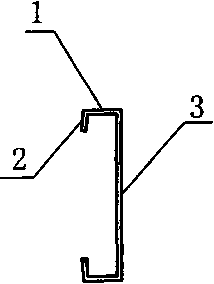
[0083] After the completion of steps (1) to ①, the steel strips cut into strips will pass through the cold bending forming unit, adopt the existing continuous rolling process of cold bending forming, and perform side hooking after multiple passes of cold bending rolling and rolling. 2. The side plate 1 is processed, and then automatically counted and cut according to the fixed length to produce the side hook 2 with a length of 3mm and the side plate 1 with a length of 5mm, and the angle between the side hook 2 and the sid...

Embodiment 2

[0114] Such as Figure 1~2 As shown in 0, the specific implementation steps of a manufacturing process of a steel-plastic composite section bar are as follows:

[0115] (1) Preparation of steel profiles

[0116] ①Cut and slitting

[0117] With embodiment 1. The feature is: the use of color-coated steel strips with a thickness of 0.7mm and a width of 1200mm.

[0118] ② Preparation of steel profiles

[0119] With embodiment 1. The feature is: the length of the side hook 2 is 4mm, the length of the side plate 1 is 6mm, and the angle between the side hook 2 and the side plate 1 is 105°, the angle between the side plate 1 and the straight web 3 is 90°, and the bottom is straight and flat 5 steel profiles in web 3 lengths:

[0120] The length of straight flat web 3 of steel profile 1 15 is 30mm, the length of straight flat web 3 of steel profile 2 14 is 67mm, the length of straight flat web 3 of steel profile 316 is 48mm, and the length of straight flat web 3 of steel profile ...

Embodiment 3

[0132] Such as Figure 1~2 As shown in 0, the specific implementation steps of a manufacturing process of a steel-plastic composite section bar are as follows:

[0133] (1) Preparation of steel profiles

[0134] ①Cut and slitting

[0135] With embodiment 1. The feature is: the use of ordinary carbon steel strips with a thickness of 1.2mm and a width of 1000mm.

[0136] ② Preparation of steel profiles

[0137]The same as in Example 1, the feature is: the side hook 2 is 5mm long, the side plate 1 is 7mm long, and the angle between the side hook 2 and the side plate 1 is 115°, and 5 kinds of steel profiles with the following straight web 3 lengths are produced:

[0138] The length of straight flat web 3 of steel profile 1 15 is 33 mm, the length of straight flat web 3 of steel profile 2 14 is 74 mm, the length of straight flat web 3 of steel profile 316 is 53 mm, and the length of straight flat web 3 of steel profile 4 17 3 is 60mm, and the length of the straight flat web 3 ...


PUM

PropertyMeasurementUnit
heightaaaaaaaaaa
thicknessaaaaaaaaaa
heightaaaaaaaaaa

Abstract

Provided is a manufacturing process of steel plastic composite materials, relating to the manufacturing process of building door and window steel plastic composite section bar. The process takes steel strip as raw material, firstly prepares the steel section bar by strip cutting and cold bending processing, manufactures plastic section bar by plastic extrusion process, and then compounds the two section bars into seven composite section bars of the patent of ''a steel plastic composite section bar'' with the application number of 200820099314.1 for the applicant. The invention has simple and mature process, less investment of production equipment, low energy consumption, high production efficiency, high intensity for produced product, excellent heat insulation performance, good appearance quality, and stable product quality. The steel plastic composite section bar manufactured by the invention can be widely used as section bars for building doors and windows such as casement window, sliding window, fixed window, top-hung window, glass casement door, sliding door, and the like.

Description

1. Technical field [0001] The invention belongs to the technical field of steel-plastic composite profiles, and in particular relates to a manufacturing process of steel-plastic composite profiles for building doors and windows. 2. Background technology [0002] Building doors and windows are mainly made of four materials: steel, plastic, aluminum, and wood, among which steel and plastic are the two materials with the greatest difference in material properties, and the density of steel is 7.8g / cm 3 , the tensile strength is 300~400Pa / m 2 , the yield strength is 230~330Pa / m 2 , the elongation rate is 28-32%, the elastic modulus is 210Gpa, and the linear expansion coefficient is 1.25X10 -5 K -1 These excellent material properties are the basis for ensuring the usability and physical quality of doors and windows, but the high thermal conductivity of steel is not conducive to the energy saving of building doors and windows; plastic doors and windows are generally made of poly...

Claims


Application Information

Patent Timeline
Patent Type & Authority Patents(China)
IPC IPC(8): E06B3/08B21D5/00B29C47/12B29C65/48B29K77/00B29K23/00B29K27/06B29C48/30
Inventor 张荣喜赖怒涛刘显萍
Owner 重庆华厦门窗有限责任公司
Learn More