Inlay for shaped charge and method of use

a technology of perforating and shaped charges, applied in the field of systems and methods of perforation, can solve the problems of increasing the cost and effort associated, the geometry of the shaped charge and the associated perforating jet is set, and the effect of increasing the cost and effor

Active Publication Date: 2019-12-31
DYNAENERGETICS
View PDF26 Cites 3 Cited by
  • Summary
  • Abstract
  • Description
  • Claims
  • Application Information

AI Technical Summary

Problems solved by technology

One disadvantage of typical shaped charges is that the geometry of the shaped charge and associated perforating jet is set when the shaped charge is manufactured according to corresponding specifications.
The limited, particularized use of different shaped charges thereby increases the costs and efforts associated with, e.g., manufacturing smaller batches of shaped charges, holding inventory of specific shaped charges, and transporting and keeping various styles of shaped charges at a job site.

Method used


Image

  • Inlay for shaped charge and method of use
  • Inlay for shaped charge and method of use
  • Inlay for shaped charge and method of use

Examples


Embodiment Construction

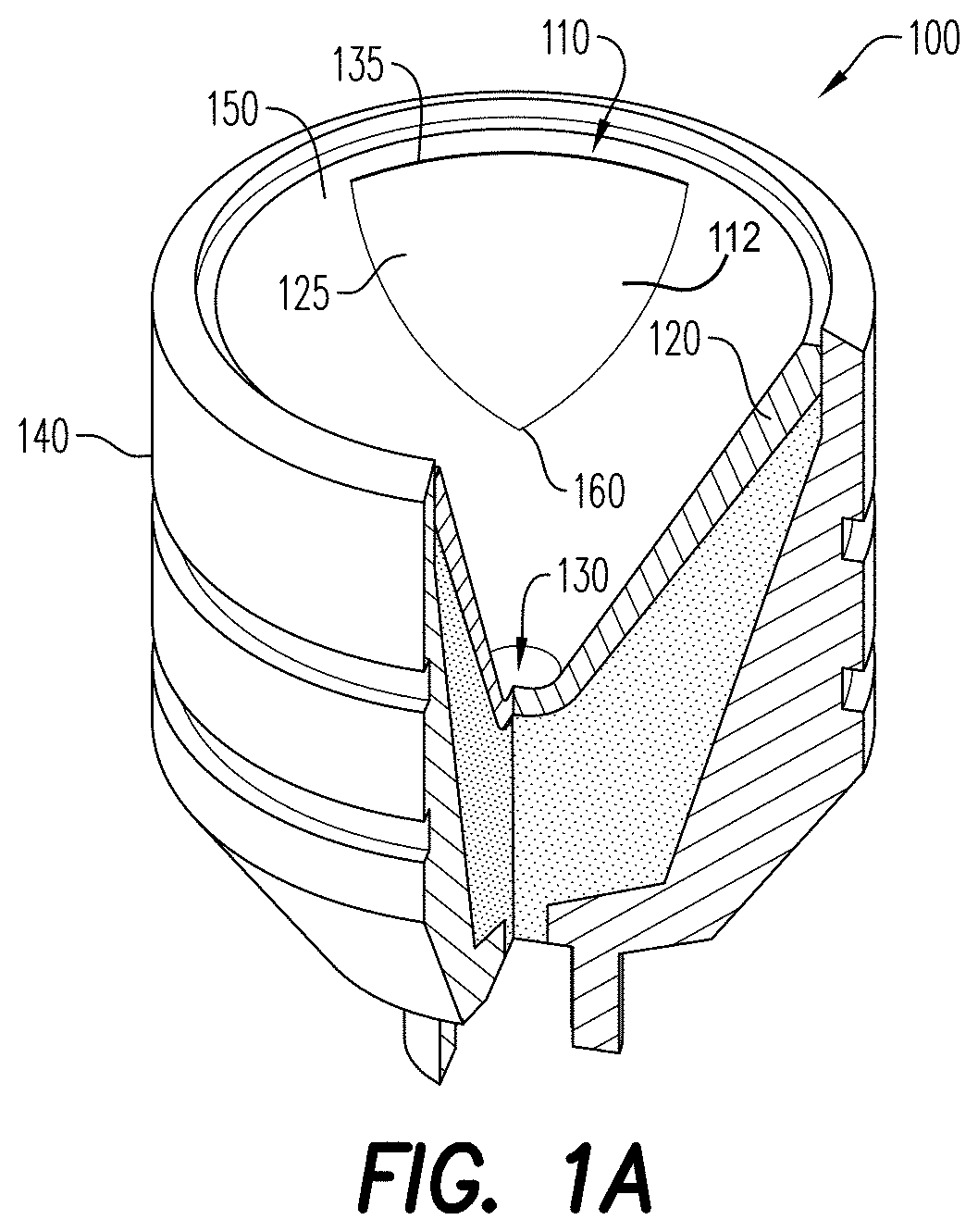
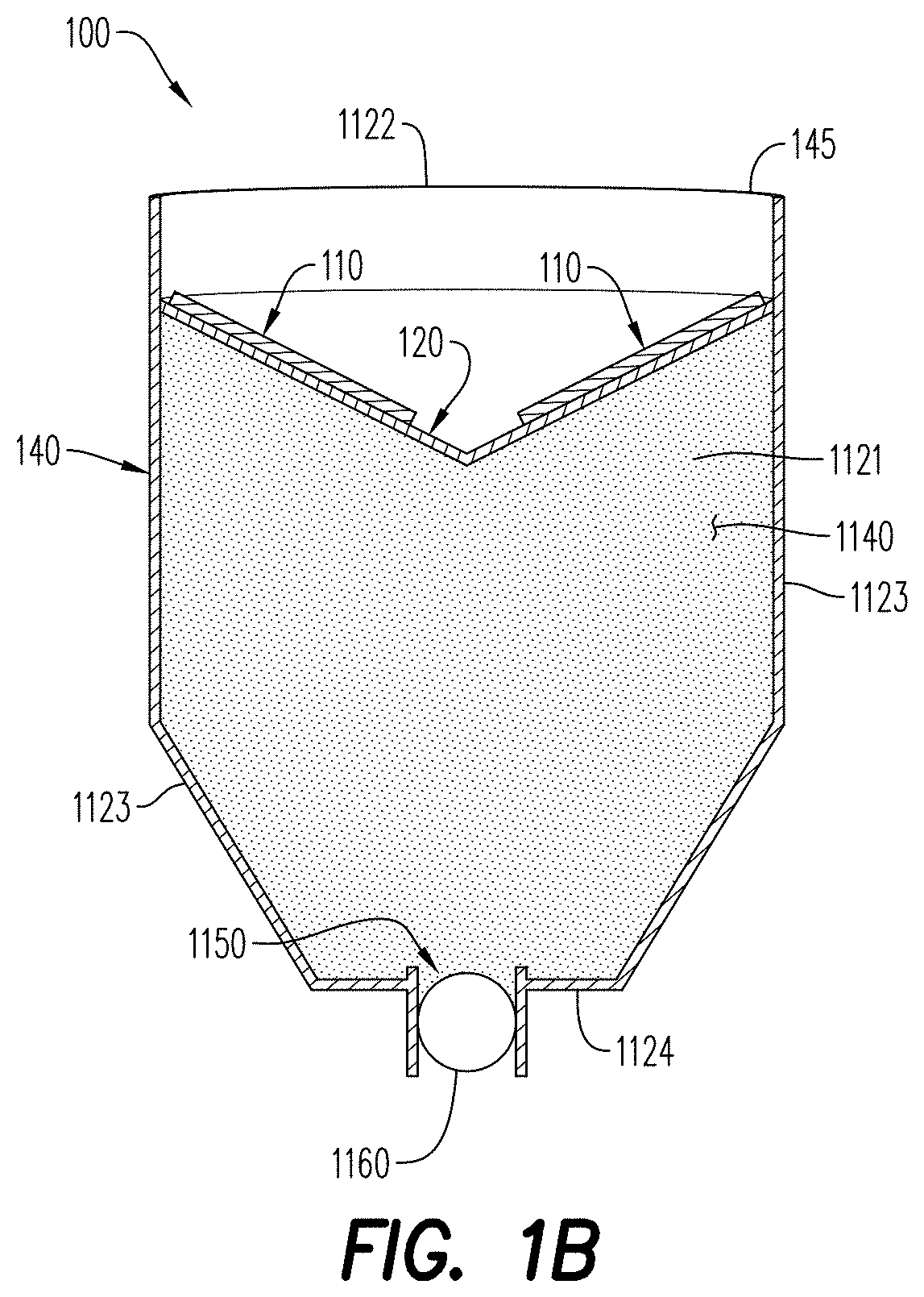
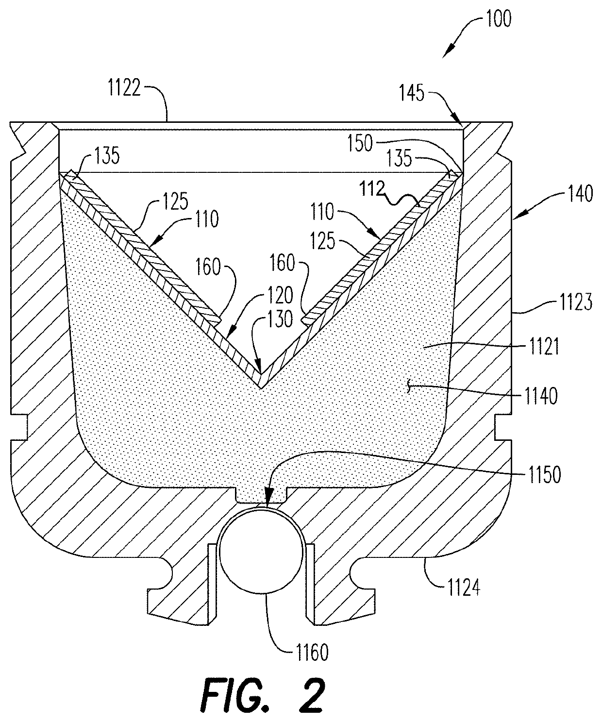
[0007]Some exemplary embodiments described herein relate to a shaped charge inlay for use with a liner in a shaped charge. The shaped charge inlay is secured to the liner, and includes an upper edge, and a distal edge opposite the upper edge. The upper edge may extend inwardly from an edge of a shaped charge case associated with a shaped charge. The shaped charge inlay further includes a body that extends between the upper and distal edges, and toward an apex of the liner. According to an aspect, at least a portion of the shaped charge inlay covers a portion of the liner that is away from the apex of the liner. The shaped charge inlay is disposed above the liner in the shaped charge in a manner that disrupts the collapse of the liner upon detonation of the shaped charge, thereby changing the geometry of a perforating jet and / or perforation created by the shaped charge. The shaped charge inlay adapts shaped charges so that the shaped charge can be used to create atypical perforation ...


PUM


Abstract

According to some embodiments, a shaped charge inlay may include an upper edge that extends inward and horizontal to an edge of a shaped charge casing associated with a shaped charge. The shaped charge includes an existing liner and the shaped charge inlay further includes a body that extends inward toward an apex of the existing liner. The shaped charge inlay may be disposed above the existing liner in the shaped charge, to disrupt collapse of the existing liner upon detonation of the shaped charge and thereby change the geometry of a perforating jet and resulting perforation created by the shaped charge.

Description

CROSS-REFERENCE TO RELATED APPLICATIONS[0001]This application claims the benefit of U.S. Provisional Application No. 62 / 654,306 filed Apr. 6, 2018, which is incorporated herein by reference in its entirety.FIELD OF THE DISCLOSURE[0002]Devices, systems, and methods for perforating, among other things, wellbore structures and oil and gas deposit formations are generally disclosed. More specifically, devices, systems, and methods for adapting a geometry of a perforating jet and resulting perforation are disclosed.BACKGROUND OF THE DISCLOSURE[0003]Perforating gun assemblies are used in many oilfield and gas well completions. In particular, the assemblies may be used for, among other things, any or all of generating holes in downhole pipe / tubing (such as a steel casing) to gain access to an oil / gas deposit formation and to create flow paths for fluids used to clean and / or seal off a well, and perforating the oil / gas deposit formation to liberate the oil / gas from the formation. The perfor...

Claims


Application Information

Patent Timeline
Patent Type & Authority Patents(United States)
IPC IPC(8): F42B1/028F42B3/08F42B1/02E21B43/117
CPCE21B43/117F42B1/028F42B1/02F42B3/08
Inventor LOEHKEN, JOERN OLAFWILL, DENISFRICKE, BERND
Owner DYNAENERGETICS
Why Eureka
Try Eureka