Apparatus, method, and system for a compact modular LED lighting source aimable on multiple independent axes

Active Publication Date: 2020-03-10
MUSCO
View PDF6 Cites 3 Cited by
  • Summary
  • Abstract
  • Description
  • Claims
  • Application Information

AI Technical Summary

Benefits of technology

The present invention provides a lighting system that allows for directional lighting, including ground-mounted facade lighting, and rapid in situ adjustability over the state of the art. The system comprises a fixture and adjustable LED modules, which can be easily replaced, added, or changed to effectuate different beam patterns. The system also includes a compact lighting source with multiple LED modules that can be individually aimed and held in place, allowing for a very wide range of aiming without interference between individual lighting sources aimed in different directions. The LED modules have good thermal transfer, can be accessed from the front, and can even allow higher driver currents, resulting in more efficient dissipation of heat. Overall, the invention provides greater flexibility and efficiency in lighting design and allows for the adjustment of LED modules in multiple directions.

Problems solved by technology

Fixtures having “aimable optics” often have additional needs, since they are frequently used for non-standardized locations and applications, such as for temporary lighting, facade lighting, lighting for building faces, signs, displays, etc.
Lighting needs for these locations may be poorly understood until the lighting is installed, or requirements may change based on trial installation of lighting or for other reasons.
The first two of these patents disclose fixtures that are adjustable or aimable in basically one dimension, which is insufficient for many special lighting applications.
They have a significant degree of aimability, but are not well-adapted for use as building lights or for placement in difficult locations or on the ground.
Further, the adjustments are not readily accessible or convenient.

Method used


Image

  • Apparatus, method, and system for a compact modular LED lighting source aimable on multiple independent axes
  • Apparatus, method, and system for a compact modular LED lighting source aimable on multiple independent axes
  • Apparatus, method, and system for a compact modular LED lighting source aimable on multiple independent axes

Examples


embodiment 1

[0033]B. Exemplary Method and Apparatus Embodiment 1

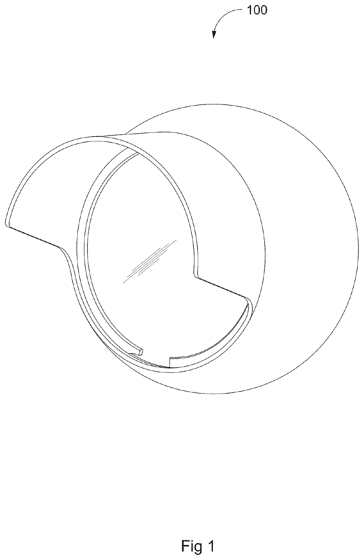
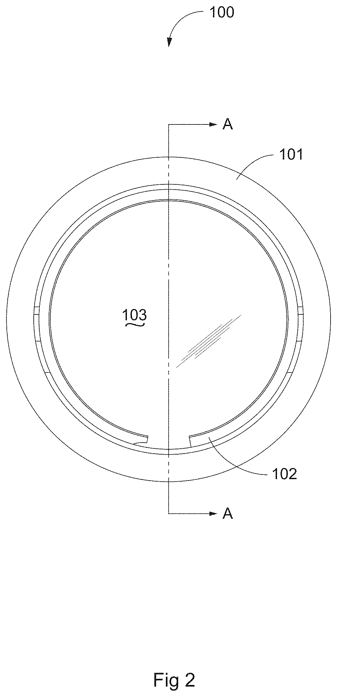
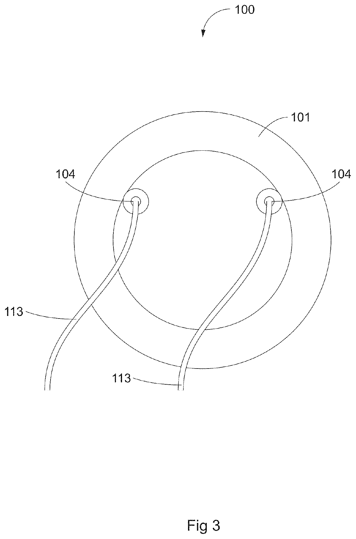
[0034]FIGS. 1-8 illustrate various views of an LED module 100 according to an embodiment of the present invention. Module 100 generally comprises a thermally conductive housing 101 having dimensions H and L on the order of 1.25″ (FIG. 4). A flat face 115 on the back of housing 101 (FIG. 3) includes holes 104 to accommodate LED power wiring run into the hollow interior of housing 101. Quick disconnect connectors for power wiring 113, FIGS. 3 and 8 could be used. This would aid switching out entire modules. A flat face on the front of housing 101 (FIG. 2) includes a visor 109 (FIGS. 4-7), (ii) an opening into the hollow interior of housing 101 readily accessible by a lighting designer (FIG. 8), and (iii) a stepped or tapered profile from the outer surface of housing 101 to the hollow interior to accommodate O-ring 106, lens 103, and snap ring 102 (FIGS. 2 and 8). The visor-like portion 109 of housing 101 of module 100 cuts off light ...

embodiment 2

[0046]C. Exemplary Method and Apparatus Embodiment 2

[0047]FIGS. 13A-16B and subparts illustrate various views of a further embodiment comprising a unit 1100 (FIG. 13A) for lighting suitable for mounting within a fixture or luminaire; itself comprising top and bottom mounting frames 1110 and 1111 respective, clamping bolts 1140, and LED modules 1113 (in this example four modules 1113).

[0048]Each LED module 1113 (FIGS. 13B, 14A-H, and 15), comprises LED capsule 1121 (FIG. 14H) and two mounting segments 1135. LED capsule 1121 comprises top capsule half 1125, bottom capsule half 1130, fasteners 1131 (FIG. 15), LED assembly 1115, and lens 1120. Fasteners 1131 are installed through holes 1133. Heads seat in counterbores 1132. Fasteners 1131 clamp capsule halves 1125 and 1130 together; however other fasteners or clamping means could be used.

[0049]LED assembly 1115 typically comprises electronics board 1116 and LED 1117, and LED power leads 1118 which are routed through lead holes 1119 in b...


PUM


Abstract

An apparatus, method, and system for a flexible approach to lighting design is discussed including temporary lighting designs, target areas with changing requirements, or tamper- and environmentally-resistant ground-mounted lighting fixtures for architectural or aesthetic lighting. Envisioned are fixtures typically comprising multiple compact LED modules mounted in one or more rows in a compact frame, capable of independent adjustment about at least two axes, having a wide range of aiming angles from a common pivotable joint, and preserving a thermal dissipation path regardless of aiming angle.

Description

CROSS-REFERENCE TO RELATED APPLICATIONS[0001]This application claims priority under 35 U.S.C. § 119 to provisional application Ser. No. 62 / 147,203 filed Apr. 14, 2015 and provisional application Ser. No. 62 / 214,356 filed Sep. 4, 2015, all of which are herein incorporated by reference in their entirety.BACKGROUND OF THE INVENTION[0002]The invention generally relates to aimable LED products. More specifically, the present invention relates to LED products which can be aimed or adjusted or which can have optical properties changed within a mounted luminaire.[0003]Fixtures having aimable LED optics are known in the industry. They have been developed because of a need to adjust and customize lighting to a desired target and for a desired effect. However, there is still room for improvement in the art.[0004]Fixtures having “aimable optics” have certain needs in common with standard lighting fixtures, including creating light that is distributed evenly on the object and at adequate levels,...

Claims


Application Information

Patent Timeline
IPC IPC(8): F21S4/00F21V14/02F21V31/03F21Y105/00
CPCF21V14/02F21V31/03F21Y2101/02F21Y2105/001F21S2/00F21V21/30F21Y2105/10F21Y2115/10
Inventor DROST, MATTHEW D.STONE, THOMAS A.
Owner MUSCO
Why Eureka
Try Eureka