Quick assembly methods and components for shade structures

a technology of shade structure and assembly method, applied in the direction of walking sticks, etc., can solve the problems of requiring rework, laborious process, and laborious prior art methods for assembly of umbrella hubs and ribs

Active Publication Date: 2020-04-28
MA
View PDF221 Cites 7 Cited by
  • Summary
  • Abstract
  • Description
  • Claims
  • Application Information

AI Technical Summary

Benefits of technology

[0005]It would be beneficial to provide structures that enable quicker and less labor intensive assembly of umbrella assemblies, e.g., rib and hub assemblies. An aspect of at least one of the embodiments disclosed herein is the realization that connection devices used in the assembly of shade structures, such as pavilions and outdoor umbrellas, can be improved to provide a more secure, quicker, and more reliable connection. Such devices can be advantageously configured with fewer parts, making them easier to manufacture than devices in the prior art. Such improved connection devices can be particularly advantageous for large shade structures.
[0006]Another aspect of at least one of the embodiments disclosed herein is the realization that umbrella rib structures can be improved to provide a more resilient retention with less friction during operation by providing a pivot member with a larger transverse dimension than pivot members of prior art umbrella rib structures. Such devices can have a longer usage life and may improve user experience by reducing noise caused during operation of the umbrella assembly.
[0007]Yet another aspect of at least one of the embodiments disclosed herein is that umbrella rib structures can be improved by integrating a removable pulley structure to provide quicker assembly and removal than existing pulley structures. A removable pulley structure can include a slot accessible from the exterior of the umbrella rib structure that can be used to insert a pulley. A removable pulley can be retained inside a slot by using a trapping member that can trap the pulley in the slot and preventing the pulley from being removed during operation. A removable pulley can provide users the freedom to determine whether or not to install a pulley to aid in operation of the umbrella assembly. Removable pulley devices can be advantageously configured with fewer parts than, for example, integrated pulley devices, making them easier to manufacture than devices in the prior art.
[0012]In another embodiment, an umbrella hub is provided that includes a central portion configured to receive an umbrella pole. The umbrella hub also includes a body that extends between the central portion and an outer periphery of the hub. The body has an engagement section adjacent to the outer periphery. The engagement section is configured to receive an end portion of an umbrella structural member. A retention structure is disposed within the engagement section. The retention structure has an elongate channel comprising a first portion comprising an access path and a second portion comprising at least one capture member that extends into the elongate channel. The capture member has a protruding surface. The protruding surface is configured to slidably accept the end portion of the umbrella structural member, such that the structural member can be directed through the first portion of the elongate channel toward the second portion thereof. In a first position, the umbrella structural member can be inserted or removed from the retention member. The umbrella structural member can be placed in a second position by rotating the umbrella structural member relative to the retention structure. In the second position, the protruding surface rotatably secures the structural member.

Problems solved by technology

Prior art methods of assembly of umbrella hubs and ribs are too labor intensive.
While achieving the result of a secure assembly of hub and ribs, this process is tedious and sometimes requires rework, for example if the ends of any of the ribs become misaligned before the upper hub portion is attached to the lower hub portion.

Method used


Image

  • Quick assembly methods and components for shade structures
  • Quick assembly methods and components for shade structures
  • Quick assembly methods and components for shade structures

Examples


Embodiment Construction

[0028]While the present description sets forth specific details of various embodiments, it will be appreciated that the description is illustrative only and should not be construed in any way as limiting. Furthermore, various applications of such embodiments and modifications thereto, which may occur to those who are skilled in the art, are also encompassed by the general concepts described herein. Each and every feature described herein, and each and every combination of two or more of such features, is included within the scope of this application provided that the features included in such a combination are not mutually inconsistent.

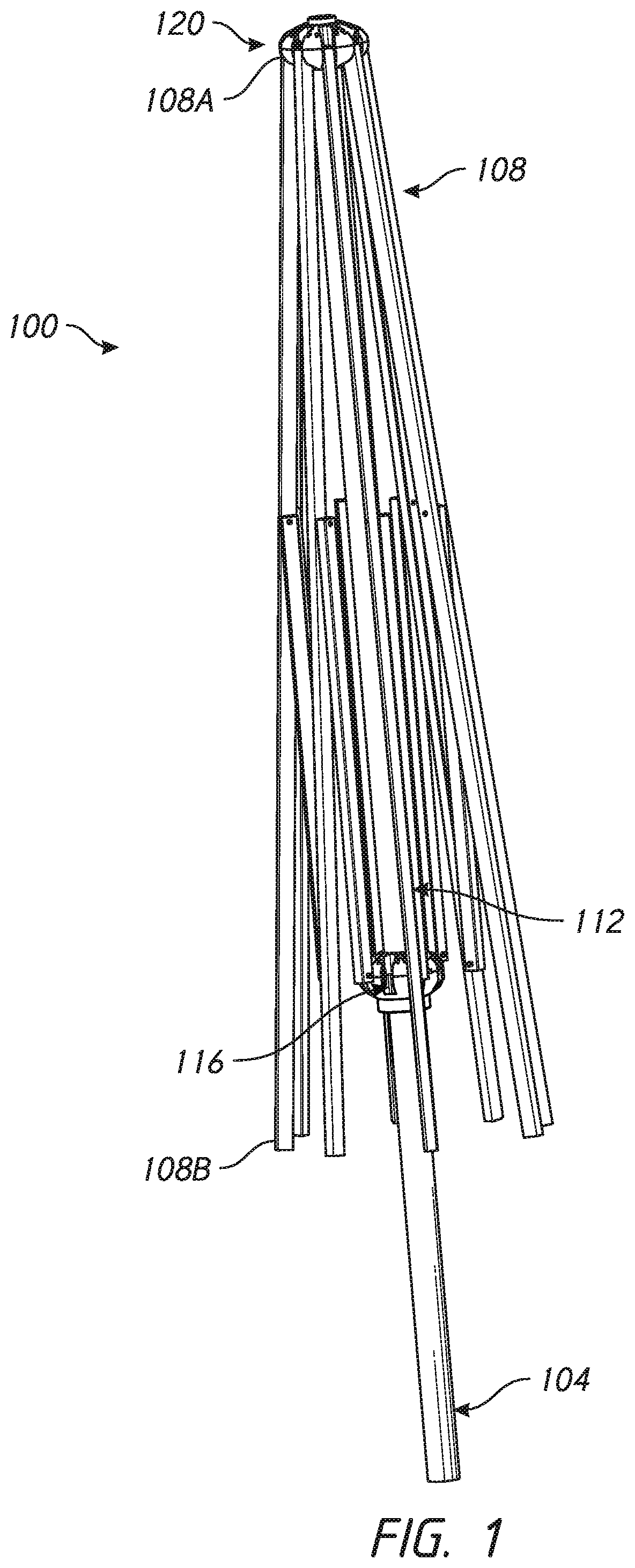
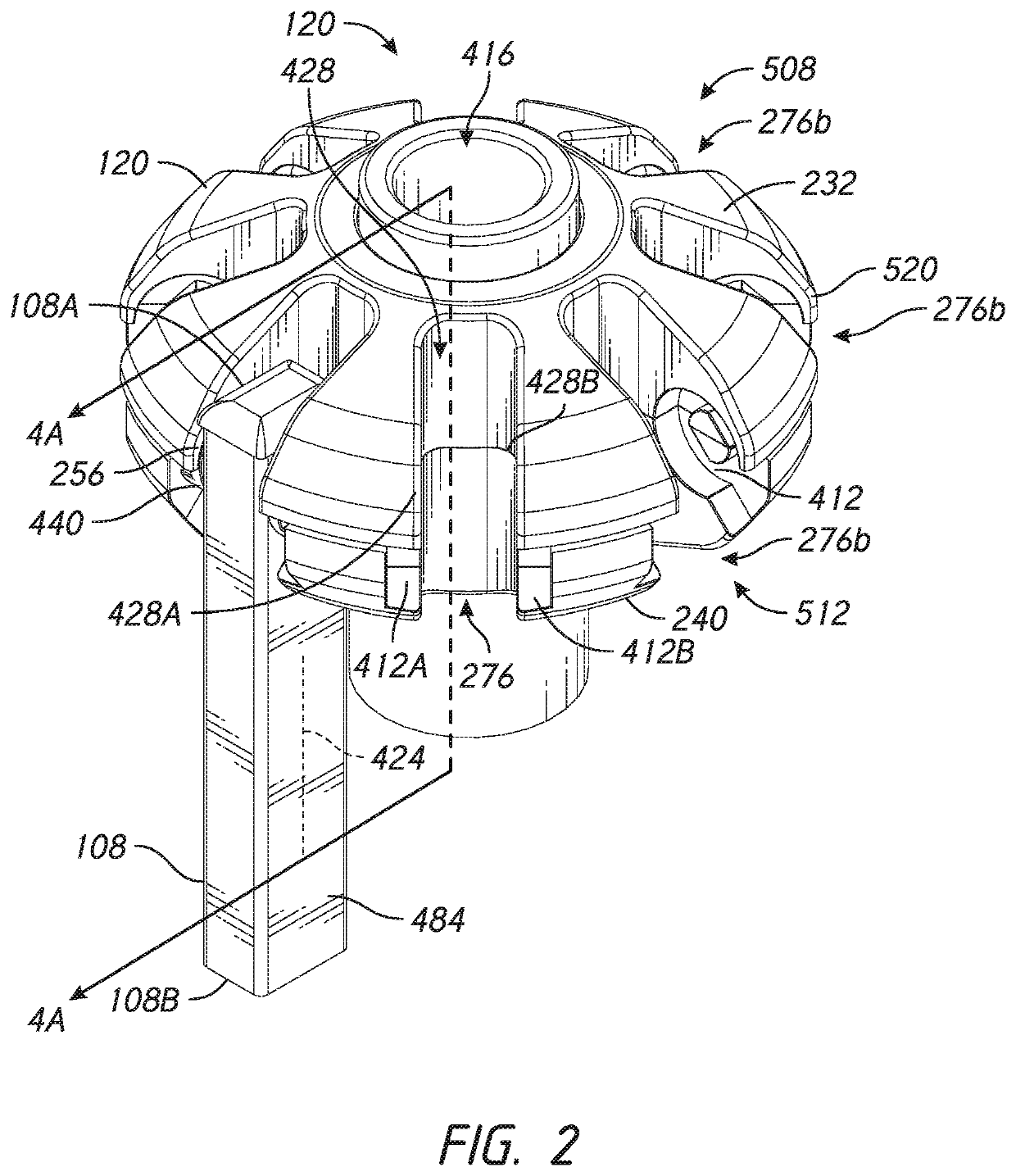
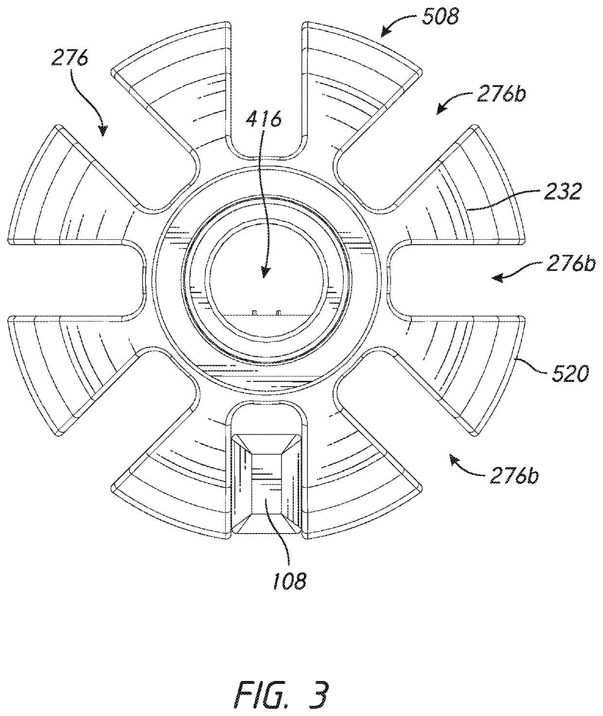
[0029]In accordance with embodiments described herein, there are provided various configurations of a hub and hub assembly that can be used with an umbrella support structure, such as an umbrella frame or pavilion frame, to facilitate the rapid and secure fastening of structural ribs with a hub or other structure. As described in greater detail herein...


PUM


Abstract

A quick connect system is provided for a shade structure. The system includes a hub and a rib. The hub has an upper portion, a lower portion, and a rib engagement section. The rib engagement section has a groove. The groove has an annular bearing zone, which may be disposed between two facing walls of the hub. The rib comprises an elongate body having an inner end and an outer end, the inner end of the rib having a pivot member. The annular bearing zone is configured to support end portion of the pivot member of the rib.

Description

INCORPORATION BY REFERENCE TO ANY PRIORITY APPLICATIONS[0001]Any and all applications for which a foreign or domestic priority claim is identified in the Application Data Sheet as filed with the present application are hereby incorporated by reference under 37 C.F.R. § 1.57.BACKGROUND OF THE INVENTIONField of the Invention[0002]This application relates to apparatuses and methods that facilitate efficient assembly of ribs and hubs of umbrellas and other structures with a plurality of elongate structural members that extend from a central portion of the hub.Description of the Related Art[0003]Large umbrellas, such as market umbrellas, generally include a frame that is used to support and distribute the weight of an upper portion of the umbrella as well as to enable the umbrella to be opened and closed as desired by the user. The frame of such umbrellas can take various forms, but often includes one or more hubs connected with a plurality of movable structural members, sometimes called...

Claims


Application Information

Patent Timeline
Patent Type & Authority Patents(United States)
IPC IPC(8): A45B25/06A45B25/02A45B25/10
CPCA45B25/06A45B25/02A45B25/10
Inventor MA, OLIVER JOEN-AN
Owner MA
Why Eureka
Try Eureka