Mechanized tail for mobile devices
a mobile device and tail technology, applied in the field of mobile or wireless vehicles, can solve the problem that many such vehicles may become positioned in undesired orientations
- Summary
- Abstract
- Description
- Claims
- Application Information
AI Technical Summary
Benefits of technology
Problems solved by technology
Method used
Image
Examples
first embodiment
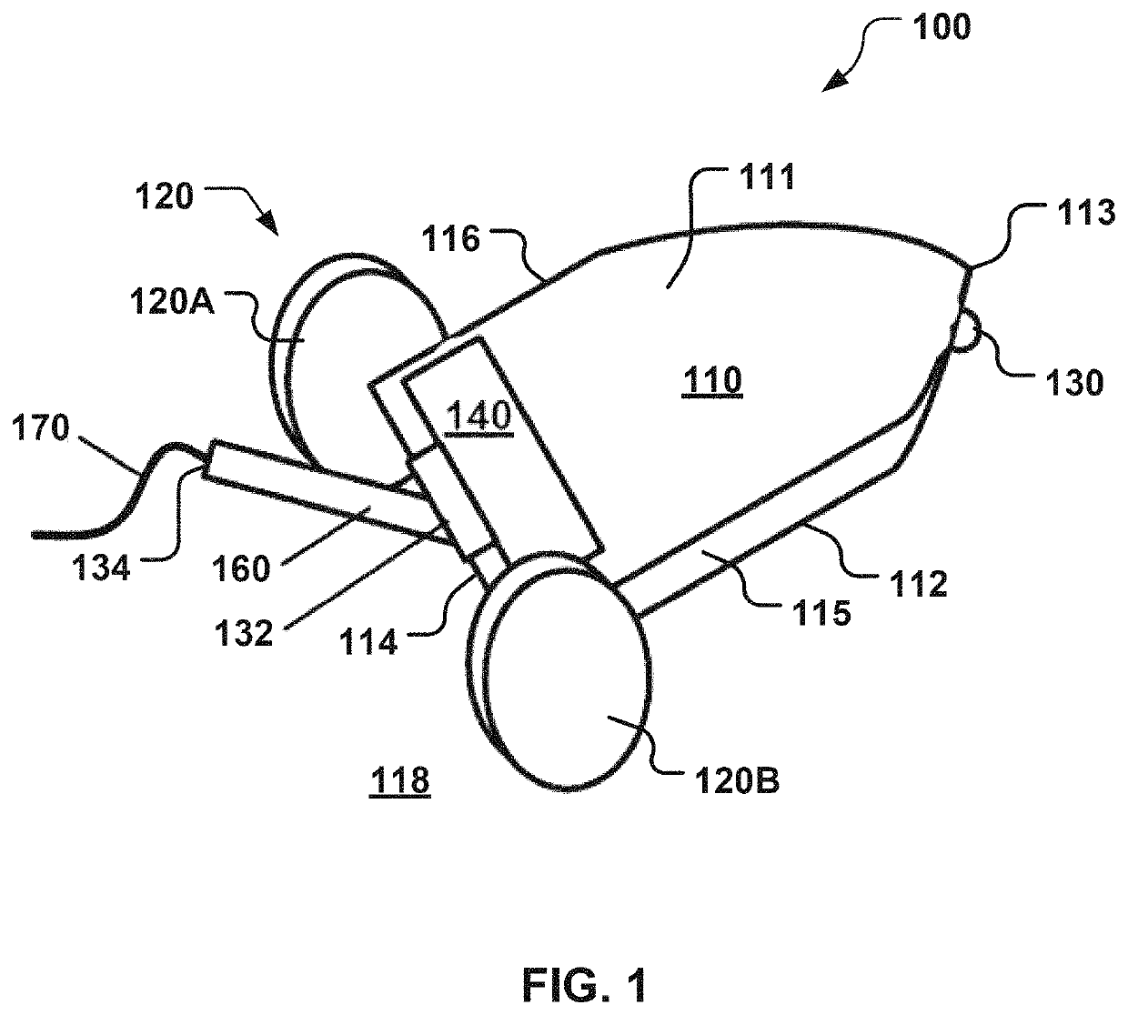
[0044]FIG. 1 illustrates the mobile device 100. Referring to FIG. 1, the mobile device 100 has a top portion 111 opposite a bottom portion 112, a front portion 113 opposite a back portion 114, and a left side portion 115 opposite a right side portion 116. Referring to FIG. 13, the mobile device 100 may include an onboard control mechanism 101, one or more sensors 102, one or more propulsion mechanisms 120, an energy source 124, a mobile device body or platform 110, a motion drive 140, and a member or mechanized tail 160.
[0045]While the mobile device 100 may be any size, in the figures and examples below, the mobile device 100 may be characterized as being toy sized. For example, the mobile device 100 may be small enough to fit within a box that is 30 centimeters (“cm”) by 30 cm by 30 cm. By way of non-limiting examples, the mobile device 100 may have a length of about 7.5 cm, a width of about 5.8 cm, and a height of about 3.5 cm excluding the mechanized tail 160. By way of additiona...
second embodiment
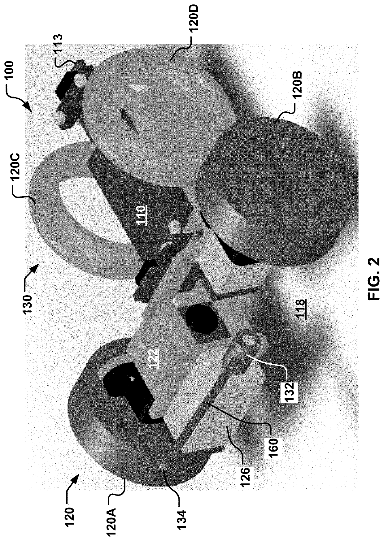
[0075]FIG. 2 is a rear perspective view of the mobile device 100 and its mechanized tail 160 as per the present disclosure. In the example illustrated in FIG. 2, the mechanized tail 160 has been constructed from copper. The mechanized tail 160 may be coupled to the gear box 126. The gear box 126 may be driven by the actuator(s) 122. Referring to FIG. 13, the processor(s) 146 may control the operation of the actuator(s) 122. In the embodiment illustrated in FIG. 2, the mobile device 100 includes the single actuator 122, which is configured to control the operation of the gear box 126. The gear box 126 moves the mechanized tail 160.
third embodiment
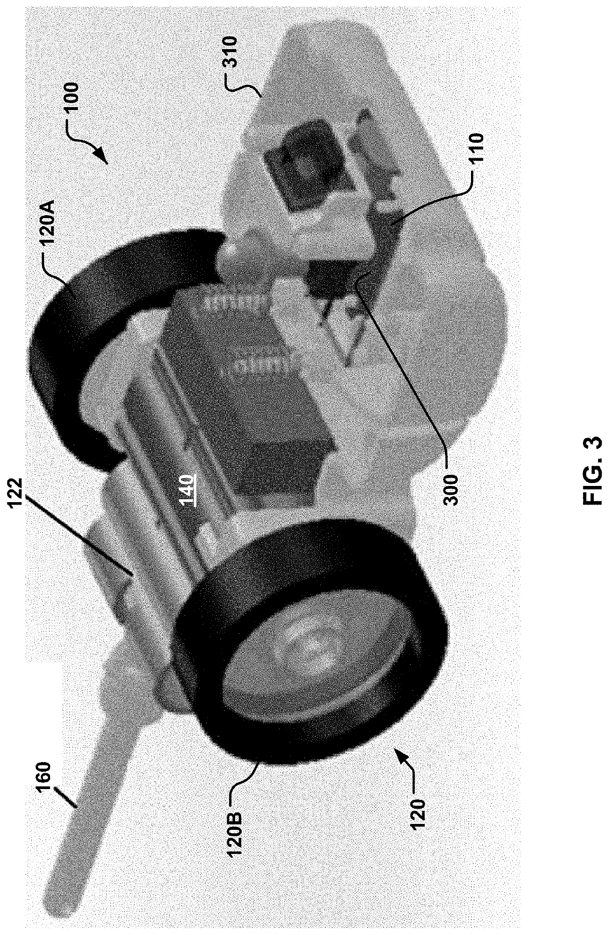
[0076]FIG. 3 is a front perspective view of the mobile device 100 with the mechanized tail 160. This illustration shows the mechanized tail 160 connected to the platform 110 via the single actuator 122. Referring to FIG. 13, the processor(s) 146 may control the operation of the single actuator 122. Referring to FIG. 3, in this embodiment, the gear box 126 (see FIGS. 2 and 13) has been omitted. The single actuator 122 is configured to control the operation of and move the mechanized tail 160.
[0077]FIGS. 4A-4C illustrate a fourth embodiment of the mobile device 100. FIG. 4A is a side view of the fourth embodiment of the mobile device 100 with the mechanized tail 160. FIG. 4B is a front perspective view of the fourth embodiment of the mobile device 100 with the mechanized tail 160. FIG. 4C is a rear perspective view of the fourth embodiment of the mobile device 100 with the mechanized tail 160.
[0078]FIGS. 14 and 15 are both front perspective views of a fifth embodiment of the mobile de...
PUM
 Abstract
Description
Claims
Application Information
 - R&D
- Intellectual Property
- Life Sciences
- Materials
- Tech Scout
- Unparalleled Data Quality
- Higher Quality Content
- 60% Fewer Hallucinations
Browse by: Latest US Patents, China's latest patents, Technical Efficacy Thesaurus, Application Domain, Technology Topic, Popular Technical Reports.
© 2025 PatSnap. All rights reserved.Legal|Privacy policy|Modern Slavery Act Transparency Statement|Sitemap|About US| Contact US: help@patsnap.com


